

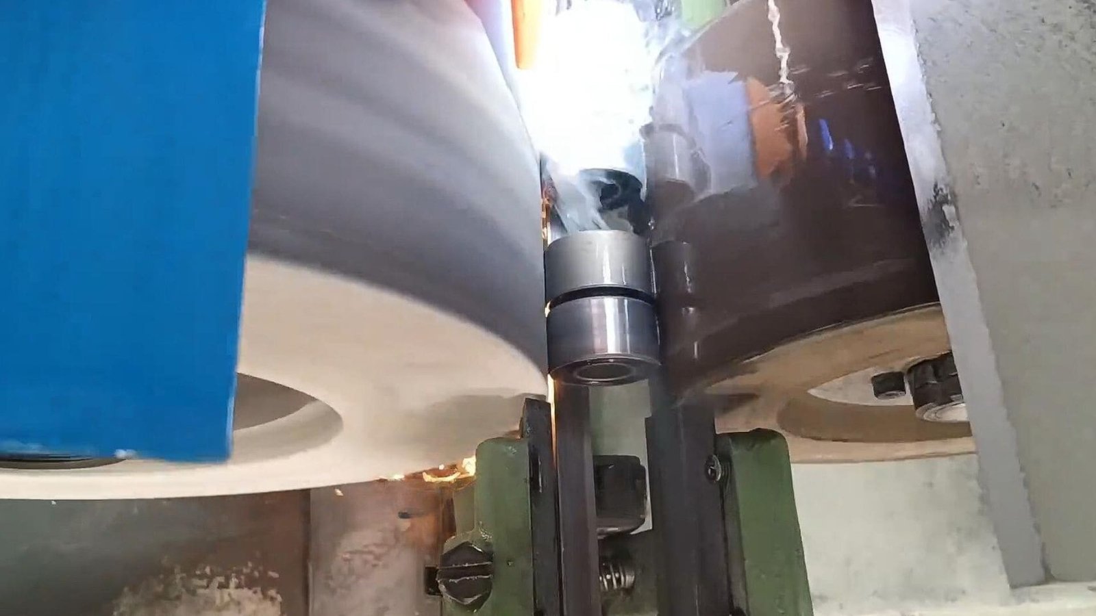
How Can Spiral Marks Be Prevented During the Centerless Grinding Process?
Seeing faint or obvious spiral lines wrapping around your otherwise perfectly ground parts? These marks ruin the cosmetic appearance and can cause rejection, indicating problems in your setup or consumables.
Spiral marks are often prevented by correctly positioning guide plates, using a hard/smooth workrest blade, maintaining clean coolant, radiusing wheel edges, setting proper center height, and ensuring the grinding wheel isn’t dull or dressed too coarsely.
Spiral marks are just one type of surface defect that can plague centerless grinding. Other issues like edge chipping, gouges, or dull finishes also require specific troubleshooting to ensure quality parts.
What Causes Chipping or Damage at the Leading Edge During Centerless Grinding Entry?
Are the front edges of your parts getting chipped or broken as they enter the grinding zone? This damages the part, potentially harms the wheels, and points to an issue with the initial contact.
Leading edge chipping is typically caused by the front guide plate protruding too far, significant misalignment between the grinding and regulating wheel faces, or attempting too much material removal right at the inlet.
At J&M Machine Tools, we find entry problems usually relate to alignment or aggressive cuts. Your insights highlight these causes:
- Front Guide Plate Protrusion1: If the front guide plate sticks out slightly ahead of the regulating wheel’s point of contact, the workpiece edge can crash into it or the grinding wheel edge improperly before being correctly supported and controlled by the regulating wheel. This impact causes chipping. The fix is to slightly retract the front guide plate so the regulating wheel makes proper contact first.
- Wheel Face Misalignment2: If the front faces (edges) of the grinding wheel and regulating wheel are not in line (one is significantly ahead of the other), the workpiece can hit the leading edge of one wheel abruptly, causing damage. Checking and adjusting the axial positions of the wheels to ensure alignment is crucial.
- Excessive Inlet Cut3: Trying to remove too much material right as the part enters can put excessive force on the leading edge before it’s fully stabilized, leading to chipping. Reducing the initial depth of cut or adjusting the setup for a gentler entry can help.
How Can Parts With Rectangular Gouges Originating From Centerless Grinding Be Fixed?
Noticing strange, rectangular gouges or dwell marks on your finished parts? This unusual defect often signals an interference problem at the exit side of the grinder, stopping proper part movement.
Rectangular gouges can often be fixed by adjusting the rear guide plate so it doesn’t contact the regulating wheel, and ensuring the rear workrest blade or support isn’t too long, allowing parts to exit freely.
This type of mark usually means the part stopped rotating or feeding momentarily while still in contact with the grinding wheel. Your research points to exit obstructions:
- Rear Guide Plate Contact: If the rear guide plate is positioned too far forward, it might actually touch the regulating wheel surface. This interference can physically stop the workpiece from rotating correctly or feeding smoothly out of the machine, causing the grinding wheel to dwell in one spot and create a gouge. The solution is to adjust the rear guide plate slightly backward (retract it) so there is clearance.
- Rear Workrest Blade/Support Too Long4: Similarly, if the workrest blade or a separate rear support piece extends too far out, a finished part might not be able to clear the grinding zone properly. This jam prevents the next part from feeding forward correctly, causing it to stall and get gouged by the grinding wheel. Reinstalling or adjusting the rear blade/support to the correct length is necessary.
How Can Angular Marks and Micro-Traces Be Eliminated From Centerless Ground Surfaces?
Seeing faint angular lines, shadows, or barely visible traces on your parts, even if they meet size specs? These subtle marks detract from a perfect finish and often indicate minor instability or uneven grinding at the exit.
Eliminating faint angular marks often involves adjusting the rear guide plate forward for better support and lowering the part center height slightly to prevent bouncing or instability as the part exits the grinding zone.
These fine imperfections suggest the grinding wasn’t perfectly consistent right up to the end of the part. Your insights focus on exit conditions:
- Rear Guide Plate Position5: If the rear guide plate is set too far back (retracted) relative to the regulating wheel surface, the workpiece loses some lateral support just as it finishes the cut. This lack of firm guidance can lead to slight deflections or uneven pressure from the grinding wheel, creating faint marks or lines. Adjusting the rear guide slightly forward to maintain consistent support is the fix.
- Part Bouncing/Jumping at Outlet: If the part becomes unstable and bounces even slightly as it exits the wheels (often linked to the part center height being set too high), this disrupts the smooth grinding action. The result can be tiny flat spots, angular marks, or inconsistent micro-traces on the surface. Carefully adjusting the part center height downward (within proper limits) can increase stability and eliminate this bouncing.
How Can a Brighter, High-Luster Finish Be Achieved With a Centerless Grinder?
Are your ground parts meeting size tolerance but look dull or matte instead of bright and shiny? Achieving a high-luster finish requires fine-tuning specific parameters beyond just basic grinding.
Achieving a brighter finish typically involves reducing the regulating wheel angle for slower traverse, using a slower dressing speed for a finer grinding wheel surface, and ensuring the regulating wheel is also dressed smoothly.
Getting that mirror-like shine is about controlling the final surface texture. Your insights point towards refining speeds and wheel surfaces:
- Regulating Wheel Angle / Traverse Speed6: A larger inclination angle on the regulating wheel pulls the workpiece through faster (in thrufeed). This faster traverse speed means less grinding time per unit of surface area and can leave a duller finish. Reducing the angle slows the part down, allowing more time for the wheel to generate a finer finish.
- Grinding Wheel Dressing Speed7: Dressing the grinding wheel very quickly results in a coarser, more open wheel surface. While good for roughing, this leaves a duller finish. Using a slower traverse speed during the final dressing pass creates a smoother, finer wheel face, which imparts a brighter finish to the workpiece.
- Regulating Wheel Dress8: The finish on the regulating wheel also matters. A coarsely dressed regulating wheel can transfer its rough texture slightly or affect the workpiece’s smooth rotation, hindering the ability to get the best finish from the grinding wheel. Ensuring the regulating wheel is dressed accurately and smoothly contributes to the overall luster.
Conclusion
Preventing spiral marks, edge chips, gouges, and achieving a bright finish requires careful setup of guides, optimal wheel dressing speeds, clean coolant, correct center height, and appropriate traverse speeds for the desired outcome.
-
Understanding Front Guide Plate Protrusion can help prevent workpiece damage and improve machining efficiency. Explore this link for detailed insights. ↩
-
Fixing Wheel Face Misalignment is crucial for optimal performance and preventing damage. Discover effective solutions in this resource. ↩
-
Learning about Excessive Inlet Cut can enhance your machining techniques and reduce chipping. Check out this informative link for more details. ↩
-
Exploring this topic can provide insights into optimizing grinding setups and avoiding production issues. ↩
-
Understanding the role of the Rear Guide Plate Position can help improve grinding accuracy and surface finish. Explore this link for detailed insights. ↩
-
Understanding the effects of wheel angle and speed can help you achieve a superior finish in grinding processes. ↩
-
Exploring this topic can provide insights into optimizing dressing techniques for better surface finishes. ↩
-
Learning about the significance of wheel dress can enhance your grinding operations and improve final product quality. ↩

Chris Lu
Leveraging over a decade of hands-on experience in the machine tool industry, particularly with CNC machines, I'm here to help. Whether you have questions sparked by this post, need guidance on selecting the right equipment (CNC or conventional), are exploring custom machine solutions, or are ready to discuss a purchase, don't hesitate to CONTACT Me. Let's find the perfect machine tool for your needs.