

Why are Chatter Marks Appearing on The Surface of CNC-Turning Workpieces?
Are you tired of those ugly, wavy chatter marks ruining your carefully planned CNC-turned parts? This all-too-common issue wastes good material, adds extra time for rework, and ultimately chips away at your profits. But understanding the cause is the first step to eliminating it.
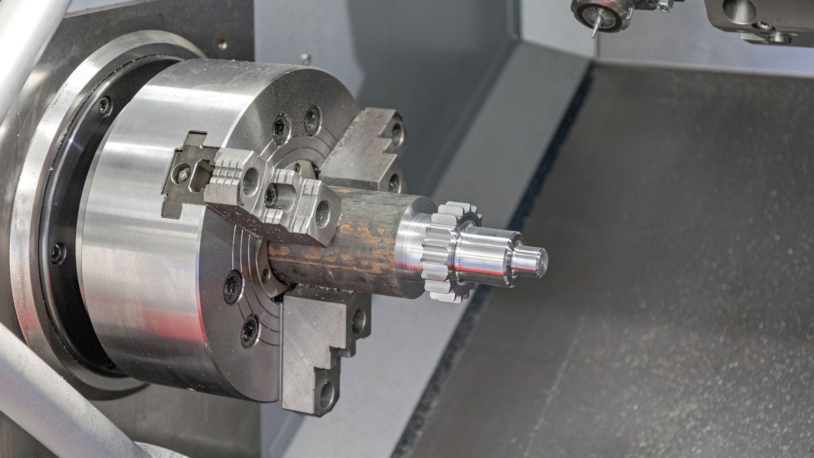
Chatter marks on CNC-turned workpieces are primarily a result of vibrations during the cutting process. The main culprits include insufficient rigidity in the machine-tool-workpiece system, using unsuitable cutting tools or incorrect tool geometry, setting inappropriate cutting parameters (like speed, feed, or depth of cut), or dealing with wear in critical machine components such as spindle bearings or guideways.

If you want to achieve those smooth, high-quality finishes that CNC turning is capable of. Let’s dive into these usual suspects.
How Does CNC Lathe Rigidity and Damping Affect Chatter Formation?
Does it seem like your CNC lathe is shaking more than it should, leaving those characteristic chatter patterns on your parts? A fundamental lack of machine stiffness or poor vibration absorption capabilities within its structure could be at the heart of the problem. This inherent weakness allows cutting vibrations to build up and spoil your work.
The overall rigidity and damping capacity of a CNC lathe are absolutely fundamental in preventing chatter. Insufficient rigidity means the machine’s structure can easily deform and vibrate when cutting forces are applied. Poor damping means these vibrations don’t die down quickly, leading to sustained chatter and a poor surface finish. Both issues significantly increase the likelihood of chatter appearing.
I always tell people to think of it like trying to write on a flimsy, wobbly table versus a heavy, solid one. The same principle applies directly to machining. A stiff, well-damped machine provides a stable, unyielding platform for the cutting tool to do its job smoothly.
The Importance of System Stiffness
When we talk about rigidity, it’s about the ability of the entire system – the machine tool itself, how the workpiece is clamped, and the cutting tool setup – to resist bending or deforming under the forces generated during cutting.
- Machine Foundation and Anchoring: A solid foundation, like a concrete floor, and proper anchoring of the machine are starting points for good overall rigidity. This minimizes any external vibrations or movements influencing the machine.
- Insufficient Rigidity Effects1: If any part of this system lacks stiffness (e.g., a slender workpiece, a tool with too much overhang, or even flex in the machine’s castings), it’s prone to deflection. This isn’t just a static bend; it leads to a decrease in what we call dynamic stiffness during the cut. This can cause cutting forces to fluctuate, triggering or worsening vibrations. This is especially noticeable during high-speed cutting.
- Mechanical Resonance2: A major cause of chatter is mechanical resonance. This occurs when the frequency of the cutting forces gets close to a natural vibration frequency of the machine tool structure or the workpiece. Improving overall rigidity helps to shift these natural frequencies away from common cutting frequencies.
Why Damping is Key to Smooth Finishes
Damping3 is the system’s ability to absorb and dissipate vibration energy.
- Insufficient Damping: If your CNC lathe system4 lacks good damping, any vibrations that start during cutting won’t dissipate easily. The vibration energy continues to circulate, worsening the chatter.
- Enhancing Damping: Practical ways to improve damping include using specialized tool holders, like hydraulic expansion types, which can help absorb some of the cutting vibrations5. For thin-walled or vibration-prone parts, sometimes filling them temporarily with materials like wax or even sand can add mass and damping to quiet them down during machining.
What Role Does Tool Selection and Geometry Play in Preventing CNC Turning Chatter?
Are you just grabbing the nearest available cutting tool or sticking with standard angles without giving it much thought? This common shortcut can feel like you’re constantly battling the machine, often resulting in those frustrating chatter marks. The reality is, selecting the right tool, with the optimal geometry for the job, can make a night-and-day difference.
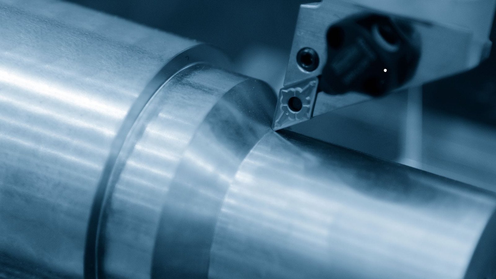
Tool selection and its specific geometry play an absolutely vital role in preventing chatter during CNC turning. Choosing the right tool material, like a tough grade of carbide, and applying suitable coatings can significantly reduce friction and wear. Furthermore, carefully optimizing tool angles such as the rake angle, major cutting edge angle, nose radius, and clearance angle helps to manage cutting forces effectively, thereby minimizing vibration and chatter.
I learned very early in my career that not all cutting tools are created equal, especially when you’re trying to eliminate chatter. A little bit of focused attention to your tooling can save you a mountain of headaches down the line.
Smart Tool Material and Coating Choices
The material your cutting tool is made from, and any specialized coating it features, directly impacts its performance and its ability to resist vibration.
- Tool Material and Stiffness: Selecting an appropriate tool material is crucial. Carbide tools6 are a common first choice due to their high hardness and wear resistance, which helps them maintain a sharp edge and resist deflection. Also, consider the tool’s physical dimensions: tools with larger diameters and shorter lengths (less overhang from the holder) tend to be much stiffer and less prone to vibration.
- Tool Coating Benefits7: Modern tool coatings are functional, not just cosmetic. Coatings like TiN, TiCN, or Al2O3 can significantly reduce friction between the tool and workpiece, leading to lower cutting forces and less heat generation, both of which help reduce vibration.
Optimizing Tool Geometry for Cutting Stability
The shape and specific angles of your cutting tool’s edge – its geometry – are critical for controlling how it interacts with the workpiece.
- Rake Angle8: A positive rake angle generally makes the tool cut more freely, reducing cutting resistance and the overall cutting forces. This, in turn, reduces the tendency for the system to vibrate.
- Major Cutting Edge Angle (Lead Angle): Adjusting this angle can change how cutting forces are distributed. A larger lead angle can sometimes thin the chip and direct forces more axially into the spindle, which can be more stable.
- Nose Radius: A larger nose radius can improve surface finish and tool strength, but an excessively large one can increase cutting forces and the likelihood of chatter. Finding the right balance is key.
- Clearance Angle: Sufficient clearance is vital to prevent the flank of the tool from rubbing on the machined surface, which causes friction and vibration.
- Chip Breakers: Tools with well-designed chip-breaking features can also contribute to a smoother cutting action by managing the chip effectively and preventing it from interfering with the cut.
- Secure Holding: Ensure the tool is held very tightly in a high-quality holder with good run-out accuracy. Any looseness here is an invitation for chatter.
How Do Cutting Parameters Influence Vibration and Chatter in CNC Turning?
Are your cutting speeds, feed rates, and depths of cut chosen carefully, or are they sometimes set without full consideration of their impact? Using cutting parameters that aren’t optimized for your specific setup can easily excite vibrations in your CNC turning operation, leading directly to those undesirable chatter marks. Finding that "sweet spot" for these settings is absolutely essential.
Cutting parameters—specifically cutting speed, feed rate, and depth of cut—have a profound influence on the development of vibration and chatter in CNC turning. Setting any of these parameters too high or too low for the given conditions can lead to unstable cutting forces, which then induce or amplify vibrations. A balanced, carefully optimized approach, avoiding extremes, is crucial for achieving smooth, chatter-free turning.
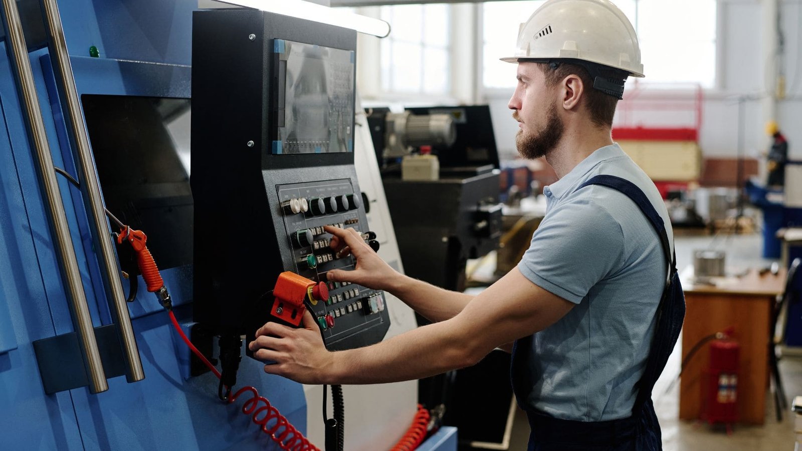
I always emphasize that you can’t just blindly copy cutting parameters from a textbook or a previous job and expect perfect results every time. You need to understand how each parameter interacts with your specific machine’s condition, the material being cut, and the tooling you’re using.
Fine-Tuning Cutting Speed
Cutting speed (the rate at which the workpiece surface passes the cutting tool) is a critical factor.
- Finding Stable Zones: Sometimes, a small adjustment to the spindle speed, say by ±5% or ±10%, can move the cutting frequency out of a range that excites a natural frequency of the machine or workpiece, thus reducing chatter. However, avoid drastic changes like halving the speed without understanding why, as you might hit another resonant frequency.
- Extremes to Avoid: Excessively high cutting speed9s can generate more heat and cause high-frequency vibrations. Conversely, very low cutting speeds can sometimes lead to a less stable cutting action and low-frequency rumble or chatter.
Maintaining a Consistent Feed Rate
The feed rate (how quickly the tool advances along or into the workpiece) determines the chip thickness.
- Consistent Chip Load: The goal is to maintain a consistent chip load. A feed rate that is too low can cause the tool to rub rather than cut cleanly, leading to instability. A feed rate10 that is too high increases cutting forces, which can overload the system and cause vibration.
- Avoiding Variability: Variable feed rates during a cut, unless intentionally programmed for a specific reason, can also lead to fluctuating cutting forces and chatter.
Managing the Depth of Cut
The depth of cut11 (how much material the tool removes in one pass) directly impacts the cutting force.
- Force Management: An excessive depth of cut generates high cutting forces, increasing the risk of chatter, tool deflection, and even tool breakage. Reducing the depth of cut is often one of the first adjustments made to combat chatter.
- Constant Engagement: For challenging cuts, strategies like using toolpaths that ensure constant tool engagement, rather than sudden entries or exits, can help maintain more stable cutting forces. If chatter is severe, consider taking multiple shallower passes instead of one deep pass.
Remember, these parameters are interconnected. Changing one will often require adjustments to others to maintain a stable cutting condition.
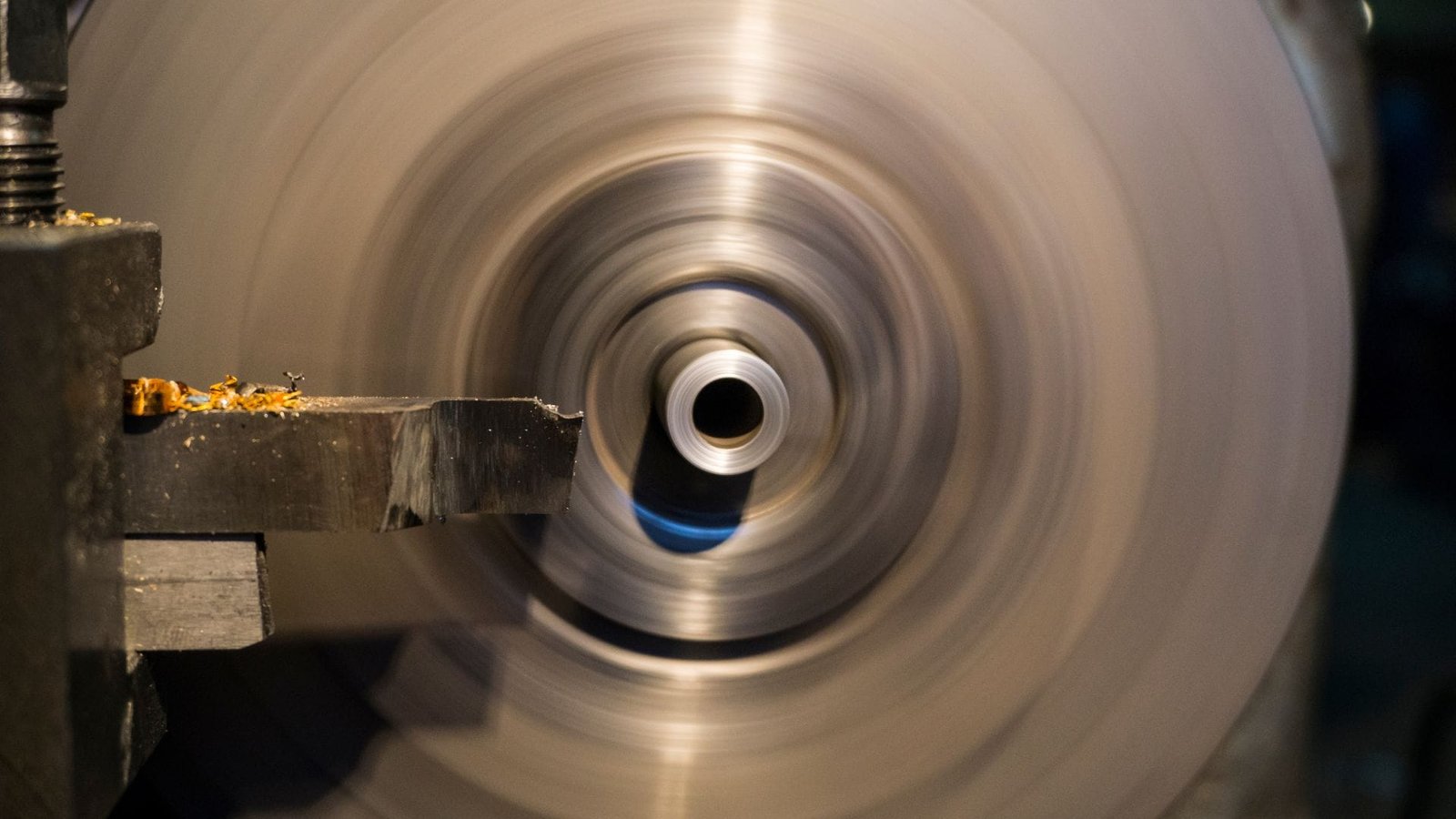
Are Worn Spindle Bearings or Guide Ways in a CNC Lathe a Potential Source of Chatter?
Has your reliable CNC lathe, which once produced consistently smooth finishes, suddenly started leaving those dreaded chatter marks on every part? If you’ve meticulously checked your tooling, workpiece setup, and cutting parameters without success, then insidious wear in critical machine components like the spindle bearings or the guideways could very well be the hidden culprit. This gradual wear slowly erodes the machine’s original precision and stability.
Yes, absolutely. Worn spindle bearings or deteriorated guideways in a CNC lathe are significant and common potential sources of chatter. Wear in spindle bearings leads to increased clearance (play), reducing the spindle’s accuracy and rotational stability. Similarly, worn or poorly maintained guideways can introduce unstable friction and allow unwanted movement or flex in the machine’s axes. Both of these conditions directly contribute to increased vibrations and the formation of chatter marks.
I’ve diagnosed this issue many times over my career. A machine that has been a solid performer for years starts to develop chatter, and often, after eliminating the more obvious causes related to tooling and programming, we discover that the root cause lies in the wear and tear of these fundamental machine elements.
How Spindle Bearing Wear Promotes Chatter
The spindle bearings12 are crucial; they support the spindle and allow it to rotate smoothly and accurately while resisting the cutting forces.
- Increased Play and Runout: Over countless hours of operation, especially under heavy loads or at high speeds, the rolling elements and raceways within spindle bearings inevitably wear. This wear increases the internal clearance, often referred to as "play" or increased runout.
- Reduced Rotational Stability: With increased play, the spindle is no longer held as rigidly. It can deflect more easily under cutting forces, leading to a loss of dynamic stiffness and rotational stability. This instability is a prime condition for chatter to develop, as the tool tip’s position relative to the workpiece becomes inconsistent.
The Connection Between Guideway Wear and Vibrations
Guideways (such as box ways or linear motion guides) are responsible for guiding the machine’s slides (carriage and cross-slide) accurately and smoothly.
- Loss of Precision and Rigidity: Wear on the surfaces of the guideways13, or on the mating components of the slides, diminishes the machine’s precision and structural rigidity. This can lead to the slides not moving as smoothly or being able to resist cutting forces as effectively.
- Unstable Friction and Stick-Slip: Worn or inadequately lubricated guideways can result in unstable friction. This might manifest as a "stick-slip" phenomenon, where the slide momentarily hesitates and then jumps forward. Such erratic motion directly translates into vibration at the cutting tool.
- Increased Clearances and Deflection: Similar to spindle bearings, wear creates excessive clearance between the guideways and the slides. This looseness means the slides are not as rigidly supported, allowing them to deflect or vibrate more easily under the dynamic loads of cutting. Regular maintenance, including lubrication and checking for excessive play in bearings and gib adjustment on guideways, is essential to mitigate chatter from these sources.
Conclusion
Chatter marks on your CNC-turned parts are a clear sign of unwanted vibrations in the system. The primary causes usually trace back to insufficient machine rigidity or poor damping, incorrect tool selection or geometry, non-optimized cutting parameters, or wear in critical machine components. By systematically addressing these areas, you can significantly improve your surface finishes and eliminate chatter.
-
Understanding the effects of insufficient rigidity can help improve machining processes and reduce errors. ↩
-
Exploring mechanical resonance can provide insights into preventing chatter and improving machining efficiency. ↩
-
Understanding damping is crucial for improving machining quality and reducing vibrations, leading to better finishes. ↩
-
Exploring the benefits of damping in CNC lathe systems can enhance your machining processes and outcomes. ↩
-
Learning about methods to reduce cutting vibrations can significantly improve the quality of your machining projects. ↩
-
Explore the benefits of carbide tools, known for their hardness and wear resistance, crucial for effective cutting performance. ↩
-
Learn how modern tool coatings enhance performance by reducing friction and heat, leading to better cutting stability. ↩
-
Understanding rake angle effects can help optimize cutting efficiency and reduce vibration, crucial for successful machining. ↩
-
Understanding cutting speed is crucial for optimizing machining processes and improving tool life. Explore this link for in-depth insights. ↩
-
Feed rate significantly influences chip thickness and cutting forces. Discover more about its impact on machining efficiency. ↩
-
The depth of cut directly affects cutting forces and tool stability. Learn more about managing this parameter effectively. ↩
-
Understanding spindle bearings is essential for maintaining machine performance and preventing issues like chatter. ↩
-
Exploring guideways will help you grasp their role in ensuring precision and stability in machining, crucial for quality output. ↩

Chris Lu
Leveraging over a decade of hands-on experience in the machine tool industry, particularly with CNC machines, I'm here to help. Whether you have questions sparked by this post, need guidance on selecting the right equipment (CNC or conventional), are exploring custom machine solutions, or are ready to discuss a purchase, don't hesitate to CONTACT Me. Let's find the perfect machine tool for your needs.