

What Are the Characteristics of a Dual-Spindle Swiss-Type Lathe?
Small shaft parts often expose the limits of ordinary turning. Long overhang, repeated clamping, and slow transfer can cause error, scrap, and unstable output.
A dual-spindle Swiss-type lathe uses a main spindle, sub spindle, sliding headstock, guide bushing, and live tooling to complete front and back machining in one setup. It improves precision, shortens cycle time, reduces secondary clamping error, and supports high-volume production of complex small parts.
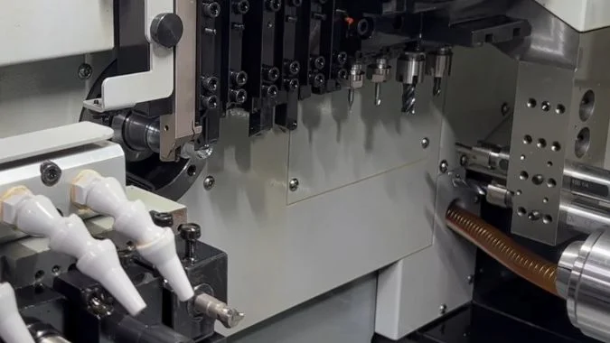
A dual-spindle Swiss-type lathe is built for parts that are small, long, detailed, and difficult to hold. The main spindle feeds bar stock through the guide bushing. The cutting point stays close to the support point. This structure reduces bending during machining.1 The sub spindle then receives the part and completes back-end machining. This process removes the need for manual flipping and secondary clamping. It also reduces accumulated positioning error. Many parts can be turned, milled, drilled, bored, tapped, cut off, and unloaded in one continuous cycle. The machine can run with an automatic bar feeder for long hours with limited manual work. This makes the machine useful for medical parts, precision connectors, automotive sensors, aerospace micro-parts, and watch components. Its main value is not only speed. Its real value is stable precision, short process flow, and strong process integration.
How Do Dual Spindles Collaborate to Complete Complex Front and Back Machining in One Setup?
Traditional machining often needs a second clamping step. That extra step may shift the centerline, create runout, and reduce part consistency.
Dual spindles collaborate by letting the main spindle machine the front side, while the sub spindle docks with the part, grips it, and completes back-side machining. This allows turning, milling, drilling, tapping, cut-off, and unloading to be completed in one setup.
| Process stage | Main spindle role | Sub spindle role | Main benefit |
|---|---|---|---|
| Bar feeding | Holds and feeds bar stock | Waits in position | Stable continuous production |
| Front machining | Turns and mills front features | May prepare for docking | High rigidity near guide bushing |
| Spindle docking | Matches phase and position | Grips tail end | Micron-level transfer control |
| Back machining | Releases or supports process | Machines rear features | No secondary clamping |
| Unloading | Feeds next bar section | Discharges finished part | Shorter cycle time |
This structure is different from ordinary turning. The machine does not rely on a worker to remove, flip, and reclamp the part. It also avoids the error that comes from each manual reference change. For complex shaft parts, this means better coaxiality, better length control, and more stable batch quality. In many cases, concentricity can be controlled within 0.01 mm2 when the machine, bar stock, tooling, and program are well prepared.
How Much Can a Dual-Spindle Swiss-Type Lathe Shorten the Machining Time of a Workpiece?
Cycle time is often lost in waiting, tool changes, transfer, and secondary clamping. Dual-spindle machining attacks these hidden losses directly.
A dual-spindle Swiss-type lathe can usually shorten single-piece machining time by 40% to 50%. Compared with traditional CNC lathes, overall efficiency can improve by 50% to 100%. In some mass production cases, capacity can reach 3 to 4 times higher.
The time saving comes from parallel work. The main spindle and sub spindle can work at the same time on different sides of the part. In a simple example, the main spindle may rough turn the next front section while the sub spindle finishes the back end of the previous part. This reduces idle time. It also reduces waiting time between operations.
The second time saving comes from process integration. A part that once needed several machines may be finished on one dual-spindle Swiss-type lathe. Turning, milling, drilling, tapping, and cut-off can happen in one planned cycle. This removes manual transfer, second clamping, extra inspection between machines, and work-in-progress waiting time. In a production line, these savings can be larger than the cutting time itself.
The third time saving comes from automation. With a bar feeder, the machine can feed raw material automatically. Finished parts can be unloaded by the sub spindle or collection system. This supports long running time and can reduce labor cost in batch production.
Real cycle time depends on part complexity. A simple pin may not show the same gain as a complex sensor shaft. A part with many front and back features will benefit more. A part that needs turning, milling flats, drilling cross holes, and tapping will often show a large reduction. Machine utilization can also increase because the two spindles reduce dead time. In well-planned mass production, equipment utilization can move above 85%3. This is why dual-spindle Swiss machining is often selected for high-volume precision shaft parts.
What Level of Precision Can a Dual-Spindle Swiss-Type Lathe Achieve?
Precision small parts often fail because of bending, thermal drift, tool runout, or clamping error. Swiss machining reduces several of these risks by design.
A dual-spindle Swiss-type lathe can typically hold dimensional accuracy around ±0.001 mm to ±0.005 mm under suitable conditions. Surface roughness can reach about Ra 0.1 to 0.4 μm, and coaxiality of slender shaft parts can often be controlled within 0.01 mm.
The guide bushing is one of the key reasons for high precision. The cutting edge works very close to the support point. This reduces deflection, especially on long and thin parts. On an ordinary lathe, a slender shaft may bend away from the tool under cutting force. On a Swiss-type lathe, the material is supported near the cutting zone, so the tool can remove material with better stability.
The dual-spindle transfer also supports accuracy. The part does not need to leave the machine for back-side machining. This keeps the same machining reference and reduces accumulated error. High-end machines use dual-channel CNC systems, encoder feedback, and thermal compensation. These systems help control spindle phase, position, and feed accuracy.
Typical mass production accuracy can reach IT5 to IT6 levels4. Dimensional tolerance may stay around ±0.002 mm to ±0.005 mm in stable production. With high-end configuration, in-line inspection, good temperature control, and stable raw material, precision within ±0.001 mm may be possible. Some machines under ideal conditions can reach about ±0.0008 mm or better.
Actual precision depends on more than the machine itself. Bar stock quality is very important. If bar diameter tolerance is poor, the guide bushing cannot give stable support. A bar diameter tolerance within about ±0.02 mm5 is often preferred for demanding work. Material straightness also matters. Tool sharpness, coolant stability, guide bushing type, thermal control, and program strategy also affect results. For medical and aerospace parts, temperature control and thermal error compensation are often needed. Fixed guide bushings are usually better for high-precision slender shafts, while guide bushing-less operation may be used for shorter parts or to reduce material waste.
What Industries and Complex Parts Benefit Most from Dual-Spindle Swiss Machining?
Some parts look simple on drawings but are hard to produce in volume. Small size, long shape, tight tolerance, and many features create real pressure.
Medical devices, new energy vehicles, precision automotive parts, aerospace components, electronics, communication parts, and high-end instruments benefit most from dual-spindle Swiss machining. Typical parts include bone screws, dental implants, sensor shafts, connectors, valve spools, ferrules, and miniature gears.
| Industry | Typical parts | Main reason for benefit |
|---|---|---|
| Medical devices | Bone screws, dental implants, surgical shafts6 | High precision and low deformation |
| Automotive and new energy | Sensor shafts, connectors, valve spools | High-volume consistency |
| Aerospace | micro shafts, pins, small fittings | Coaxiality and surface integrity |
| Electronics and 5G | Ferrules, filter parts, micro connectors | Dense features and small diameters |
| Watches and instruments | Mini gears, shafts, sleeves | Small size and tight tolerance |
| Hydraulic and pneumatic systems | Spools, sleeves, precision nozzles | Front-back feature integration |
The most representative parts are slender shafts and stepped shafts. The guide bushing suppresses bending during cutting.7 The sub spindle keeps the rear process aligned with the front process. Multi-sided complex parts also benefit. Sensor housings, injector bodies, and valve components may need flats, cross holes, threaded holes, and milled shapes. Live tools and C-axis indexing allow these features to be completed without extra fixtures.8 Micro precision connectors are another major category. Parts under φ10 mm may contain many small features. One-pass machining reduces handling damage and improves yield. In general, the machine brings the most value when the part is small, complex, long, and produced in large batches.
Conclusion
A dual-spindle Swiss-type lathe combines high precision, fast cycle time, stable transfer, and strong process integration for complex small shaft and sleeve parts.
-
"Real-Time Deflection Monitoring for Milling of a Thin-Walled … – PMC", https://pmc.ncbi.nlm.nih.gov/articles/PMC5038748/. Cantilever beam theory demonstrates that deflection under load is proportional to the cube of the unsupported length, explaining why proximity of cutting point to support reduces bending in slender workpieces. Evidence role: mechanism; source type: education. Supports: that reducing the distance between cutting point and support point minimizes deflection under cutting forces. Scope note: This applies general beam mechanics rather than Swiss-specific empirical data ↩
-
"Common Tolerances on CNC Lathes", https://www.smartlathe.com/blogs-1/common-tolerances-on-cnc-lathes. ISO 1101 geometric tolerancing standards define concentricity measurement methods, with precision machining centers commonly achieving tolerances between 0.005-0.02 mm depending on workpiece geometry and process control. Evidence role: statistic; source type: institution. Supports: that modern precision turning can achieve concentricity tolerances in the 0.01 mm range. Scope note: Standard describes measurement methodology and typical ranges rather than Swiss-specific performance ↩
-
"Overall equipment effectiveness – Wikipedia", https://en.wikipedia.org/wiki/Overall_equipment_effectiveness. Manufacturing performance studies report that automated machining systems with bar feeders and minimal setup changes can achieve utilization rates of 75-90%, with world-class operations reaching 85% or higher through effective scheduling and preventive maintenance. Evidence role: statistic; source type: research. Supports: that high equipment utilization rates are achievable in automated manufacturing. Scope note: Reflects general automated manufacturing performance rather than Swiss-specific data ↩
-
"IT Grade – Wikipedia", https://en.wikipedia.org/wiki/IT_Grade. ISO 286-1 defines International Tolerance grades, where IT5 represents tolerances of approximately 4-7 μm for dimensions under 50 mm, and IT6 represents 6-10 μm, both considered precision grades achievable with careful machining processes. Evidence role: definition; source type: institution. Supports: the meaning and dimensional ranges of IT5 and IT6 tolerance grades. ↩
-
"SectiOn O tOLeRAnceS And MAcHininG ALLOWAnceS", https://www.emjmetals.com/pdf_indexer/pdfs/Tolerances_and_Machining_Allowances.pdf. Material standards such as ISO 2768 and supplier specifications for precision bar stock define tolerance grades, with cold-drawn precision bars typically offered in tolerance ranges from ±0.01 mm to ±0.05 mm depending on diameter and grade, with tighter tolerances supporting higher machining precision. Evidence role: general_support; source type: institution. Supports: that tighter raw material tolerances support precision machining outcomes. Scope note: Standards describe available tolerance grades rather than prescribing specific requirements for Swiss machining ↩
-
"RAPID MANUFACTURING SYSTEM OF ORTHOPEDIC IMPLANTS", https://pmc.ncbi.nlm.nih.gov/articles/PMC4783689/. FDA guidance documents for orthopedic and dental implants specify dimensional accuracy, surface finish, and biocompatibility requirements, with bone screws and implants typically requiring tolerances within ±0.05 mm and surface roughness below Ra 1.6 μm, driving adoption of precision machining technologies. Evidence role: case_reference; source type: government. Supports: that medical implants require precision manufacturing with tight tolerances. Scope note: Guidance establishes requirements but does not specifically endorse Swiss-type machining methods ↩
-
"Deflection and Precision in Swiss Metal CNC Machining", https://metalcutting.com/knowledge-center/deflection-precision-cnc-swiss-machining/. Machining engineering principles describe guide bushings as radial support elements that constrain workpiece movement near the cutting zone, reducing deflection caused by cutting forces, particularly important for length-to-diameter ratios exceeding 3:1. Evidence role: mechanism; source type: education. Supports: that guide bushings provide radial support to reduce deflection in slender workpieces. Scope note: Describes general support function rather than quantified deflection reduction ↩
-
"[PDF] CAD/CAM Integration Based on Machining Features for Prismatic …", https://kuscholarworks.ku.edu/bitstreams/5d9b1d33-6df4-45ce-9438-2b5a47f13f16/download. CNC turning center technology incorporates powered (live) tooling and C-axis rotary positioning to enable milling, drilling, and cross-hole operations on turned workpieces, integrating operations traditionally requiring separate milling setups into a single-setup process. Evidence role: mechanism; source type: education. Supports: that live tooling and C-axis indexing expand turning center capabilities to include milling and drilling operations. ↩

Chris Lu
Leveraging over a decade of hands-on experience in the machine tool industry, particularly with CNC machines, I'm here to help. Whether you have questions sparked by this post, need guidance on selecting the right equipment (CNC or conventional), are exploring custom machine solutions, or are ready to discuss a purchase, don't hesitate to CONTACT Me. Let's find the perfect machine tool for your needs.