

What Are the Differences Between BT and BBT Toolholders?
You invest in high-end CNC machines, but are you losing accuracy because of a simple gap in your toolholder? Understanding the distinction between standard BT and dual-contact BBT systems is crucial for precision manufacturing.
The primary difference lies in the contact surface. Standard BT holders only contact the spindle via the taper, leaving a gap between the flange and spindle face. BBT holders feature a dual-contact design, touching both the taper and the spindle face simultaneously, which eliminates this gap and significantly boosts rigidity.
Standard BT holders have been the industry workhorse for decades, but they have physical limitations when you push them hard. The BBT system (often called "Big Plus" or dual-contact) solves these limitations by changing how the holder sits in the spindle. Let’s look at the specific design changes that make BBT unique.
What Are the Structural Designs of the BT Toolholder and the BBT Toolholder?
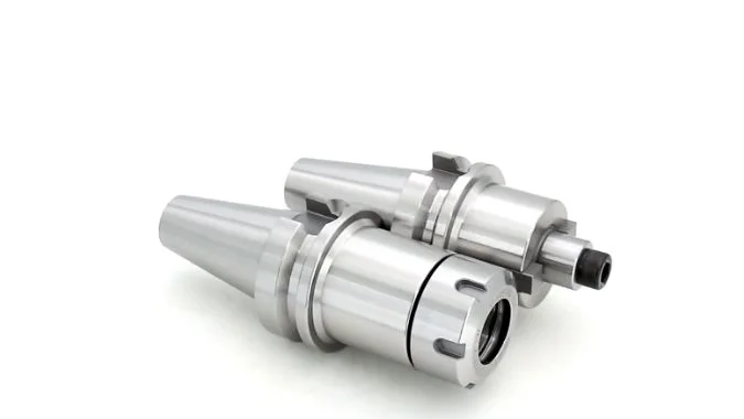
At a glance, these two holders look nearly identical, but a closer look at the flange and taper reveals the engineering magic that sets them apart.
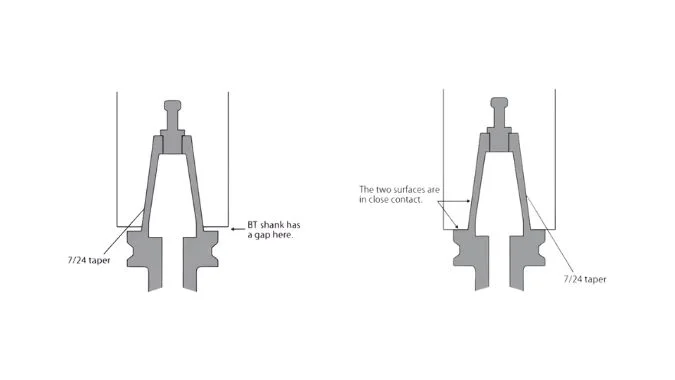
The BT holder uses a 7:24 taper ratio and relies solely on this cone shape for alignment, leaving a visible gap of about 3mm at the flange. The BBT holder uses the same taper dimensions but modifies the flange and spindle face tolerances to ensure simultaneous contact at both points.
To understand the structure, we have to look at the basics of the "BT" design. BT stands for "Morse Taper1" with a specific shank construction used globally. The core geometry is the 7:24 taper. This means that for every 24mm of axial length, the diameter of the shank decreases by 7mm. You see this across all standard sizes, whether it is the smaller BT30, the standard BT40, or the heavy-duty BT50.
In a classic BT setup, the connection is simple. The tapered shank is pulled into the spindle by the pull stud. It wedges itself tight. However, the manufacturing standards for BT are designed so that the flat face of the holder (the flange) never touches the nose of the spindle. There is typically a gap of around 3mm. This gap ensures the taper seats fully without interference.
The BBT structural design changes this rule. Developed originally by Big Daishowa, this "Dual Contact" system2 tightens the tolerances significantly. The elastic deformation of the spindle is calculated into the design. When the drawbar pulls the BBT holder up, the taper touches first, and as the spindle expands slightly under the clamping force, the face of the holder makes firm contact with the face of the spindle. It closes that 3mm gap completely. To achieve this, both the holder and the spindle must be ground to exact specifications.
Structural Comparison
| Feature | Standard BT System | BBT Dual-Contact System |
|---|---|---|
| Taper Ratio | 7:24 | 7:24 |
| Contact Area | Taper Only | Taper + Spindle Face |
| Flange Gap | ~3mm Gap | 0mm (Full Contact) |
| Manufacturing Origin | Global Standard (MAS 403) | Big Daishowa (Japan) |
What Makes a Dual-Contact System Superior to a Taper-Only System in Terms of Rigidity?
When you run a machine at high speeds, physics starts to work against you. The structural gap in standard holders becomes a weak point that kills rigidity.
Dual-contact systems are superior because the face contact acts as a hard stop, preventing the tool from being pulled into the spindle by centrifugal force. This additional support point increases overall rigidity by 20% to 30% compared to taper-only systems, drastically reducing vibration and deflection.
Let’s dive into why that 3mm gap in standard BT holders is such a problem. When I run a spindle at high RPM—say, 12,000 to 18,000 RPM—centrifugal force takes over. The spindle shaft rotates so fast that the mouth of the spindle actually expands outward. It opens up like a bell.
In a standard BT system, the only thing holding the tool in place is the taper. When the spindle mouth opens, the holder loses that tight wedge fit. The drawbar force then pulls the holder deeper into the spindle. We call this "pull-in." This is a nightmare for precision. It changes your Z-axis position, meaning your tool is now cutting deeper than you programmed.
The BBT system stops this physically. Because the flange of the holder is pressed firmly against the face of the spindle, the tool cannot be pulled back. The face contact acts as a rigid barrier. This dual support creates a wider base for the tool and absorbs vibration energy. Our insights show that this design increases overall spindle rigidity3 significantly.
Performance Impact Data
| Performance Metric | BT Toolholder | BBT Toolholder | Improvement |
|---|---|---|---|
| Spindle Rigidity | Baseline | +20% to 30% | Significant stability increase |
| Z-Axis Pull-In4 | Occurs at High RPM | Eliminated | Better depth accuracy |
| Vibration | Higher (Prone to Chatter) | Suppressed | Smoother surface finish |
Can Upgrading from Standard BT to BBT Directly Result in Longer Cutting Tool Life?
Carbide tools are expensive. If your holder is vibrating, you are essentially hammering your fragile end mills to death with every rotation.
Yes, upgrading to BBT directly extends tool life by stabilizing the cutting edge. The increased rigidity prevents micro-vibrations and chatter, which are the leading causes of chipped corners and premature failure in carbide tooling, allowing for consistent wear patterns.
You can buy the most expensive coated end mill5 in the world, but if you put it in a loose holder, it will fail. Carbide is incredibly hard, but it is also brittle. It hates vibration.
In a standard BT system, that tiny bit of movement allowed by the gap—even if it is microscopic—causes "fretting." Fretting is a type of wear caused by micro-vibrations between the holder and the spindle. This vibration travels down to the cutting edge. When the tool enters the cut, if it vibrates, the corners of the end mill chip off. Once the coating is chipped, heat builds up, and the tool burns out.
The BBT system6 locks the tool in place. Because the face contact prevents the tool from rocking or tilting under heavy load, the cutting edge enters the material smoothly every time. The "chatter" is suppressed. This means you can often run at higher feed rates without damaging the tool. We have seen cases where simply switching to dual-contact holders doubled the life of an end mill in difficult materials like titanium or stainless steel.
What Are the Compatibility Limitations When Mixing BT and BBT Holders and Spindles?
You might worry that switching to BBT means throwing away your old tools. Fortunately, the design allows for some flexibility, but you need to know the rules.
BBT and BT toolholders are generally interchangeable, meaning they will fit and function in each other’s spindles. However, you only achieve dual-contact benefits when a BBT holder is paired with a BBT spindle; mixing them results in a standard taper-only connection with reduced rigidity.
One of the best things about the BBT design7 is that it doesn’t force you to scrap your inventory. The manufacturers kept the basic geometry the same. However, you need to manage your expectations regarding performance.
You can mix and match, but the results vary. If you put a standard holder in a BBT spindle, it works, but you lose the "dual contact" magic because the holder face isn’t ground to touch the spindle. Conversely, if you put a BBT holder in an older standard spindle, the spindle face isn’t prepared to receive it, so you again get a gap. To make this easy to understand, I have broken down the combinations below.
Compatibility Matrix
| Holder Type | Spindle Type | Face Contact? | Resulting Performance |
|---|---|---|---|
| BBT Holder | BBT Spindle | YES | High Rigidity (Dual Contact) |
| BT Holder | BBT Spindle | NO | Standard Rigidity (Gap exists) |
| BBT Holder | BT Spindle | NO | Standard Rigidity (Gap exists) |
Note: While mixing is safe for general work, always use a matched BBT set for high-precision or heavy-duty operations to avoid uneven wear on the spindle taper over time.
Conclusion
Standard BT holders leave a gap, causing instability. BBT holders use dual contact to close this gap, increasing rigidity by up to 30%, extending tool life, and ensuring high-speed accuracy.
-
Understanding Morse Taper is essential for grasping the fundamentals of tool holder designs and their applications in machining. ↩
-
Exploring the BBT Dual-Contact System will provide insights into advanced clamping technologies that enhance precision and performance. ↩
-
Understanding spindle rigidity is crucial for improving machining accuracy and performance, making this resource invaluable. ↩
-
Exploring Z-Axis Pull-In will help you grasp its impact on tool depth accuracy, essential for high-quality machining. ↩
-
Explore this link to understand how coated end mills enhance performance and longevity in machining applications. ↩
-
Discover the advantages of the BBT system for tool stability and performance, ensuring better machining results. ↩
-
Explore this link to understand the innovative BBT design and how it enhances performance without requiring inventory changes. ↩

Chris Lu
Leveraging over a decade of hands-on experience in the machine tool industry, particularly with CNC machines, I'm here to help. Whether you have questions sparked by this post, need guidance on selecting the right equipment (CNC or conventional), are exploring custom machine solutions, or are ready to discuss a purchase, don't hesitate to CONTACT Me. Let's find the perfect machine tool for your needs.