

What Factors Affect the Drilling Speed of CNC High-Speed Drilling Machines?
A fast spindle does not guarantee fast drilling. Poor tool selection, deep holes, difficult materials, and blocked chips can quickly cause wear, breakage, and downtime.
The drilling speed of a CNC high-speed drilling machine depends on hole depth and diameter, workpiece material, tool material and geometry, spindle power, machine rigidity, coolant delivery, chip evacuation, and required hole quality. The best setting balances spindle speed, feed rate, tool life, and process stability.
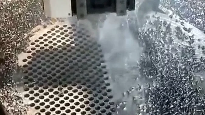
Max spindle speed is merely a theoretical upper limit. In actual machining, severe chip resistance, deep-hole friction, material hardness, and physical heat build-up act as direct barriers that restrict effective drilling speeds far below the machine’s rated capacity. Pushing RPM against these physical constraints leads only to tool overload, friction, and premature failure.
How Does Hole Depth-to-Diameter Ratio Limit Maximum Drilling Speed?
A drilling process may remain stable near the hole entrance and fail deeper inside. Longer chip paths increase heat, friction, deflection, and the risk of sudden tool breakage.
As the hole depth-to-diameter ratio increases, drill rigidity decreases and chip evacuation becomes more difficult. Speed and feed may need to be reduced, while internal coolant, specialized drill geometry, pilot holes, or peck cycles may become necessary to maintain accuracy and prevent failure.
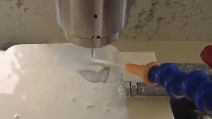
Why Does a High L/D Ratio Reduce Process Stability?
The depth-to-diameter ratio divides the drilled depth by the nominal hole diameter. A 50 mm deep hole drilled with a 10 mm tool has an L/D ratio of 51. The same depth with a 2.5 mm drill has an L/D ratio of 20.
A longer and thinner tool has lower bending rigidity. Small radial forces can then create greater drill-point movement. Runout, an uneven entry surface, fixture vibration, or incorrect point geometry may push the drill away from its intended centerline. The resulting hole can show poor straightness, oversize diameter, wall marks, or tool breakage.
Tool overhang also matters. An unnecessarily long holder and drill assembly reduces rigidity even when the actual hole is shallow. The shortest practical tool and holder arrangement usually supports higher feed and better accuracy.
A high L/D ratio also lengthens the chip evacuation path. Chips must move through the flutes while coolant moves toward the cutting zone. Packed chips increase friction and torque. The added heat can soften the cutting edge, damage its coating, or weld material to the drill.
| Approximate L/D range | General process condition | Common drilling approach |
|---|---|---|
| Up to 3 | Short and stable hole | Standard parameters may be possible |
| 3–5 | Normal production drilling | Stable coolant and chip control required |
| 5–10 | Moderately deep hole | Internal coolant and reduced parameters may be needed |
| 10–20 | Deep-hole drilling | Specialized geometry, pilot entry, and careful monitoring |
| Above 20 | Specialized deep-hole application | Gun drilling, BTA drilling, or another dedicated process2 |
These ranges are guides rather than universal limits. Modern solid-carbide drills with internal coolant may drill relatively deep holes without pecking. In contrast, an HSS drill with external coolant may require pecking at a much lower L/D ratio.
Should Speed Always Be Reduced as the Hole Becomes Deeper?
A fixed percentage reduction for every increase in L/D should not be applied to every process. Tool manufacturers provide separate parameter recommendations for short, long, and extra-long drills. Some deep-hole tools retain a reasonable cutting speed but use a lower feed, a controlled entry sequence, and higher coolant pressure.
Peck drilling can break chips and clear the flutes, but every retract adds non-cutting time. Repeated full retraction may also create rubbing, thermal cycling, and re-entry marks. A properly selected internal-coolant drill may complete the hole faster with one continuous feed.
The process bottleneck shifts as depth increases. Short-hole performance is often limited by spindle power, tool capability, or feed acceleration. Deep-hole performance is more often limited by tool dynamics, chip evacuation, coolant flow, straightness, and thermal control. Productive speed must therefore be based on the entire hole-making system rather than rpm alone.
What Impact Does Workpiece Material Have on Drilling Speed?
The same drill can perform well in aluminum and fail quickly in stainless steel. Material hardness, toughness, heat flow, abrasiveness, and chip shape change the safe cutting range.
Workpiece material controls allowable cutting speed through hardness, strength, thermal conductivity, work-hardening behavior, abrasiveness, and chip formation. Aluminum generally permits high speeds, while stainless steel, titanium, hardened steel, and nickel-based alloys often require lower speeds, stronger tooling, and more effective cooling.

How Do Hardness and Thermal Properties Affect Speed?
Hard materials increase pressure at the cutting edge. They can accelerate abrasive wear and edge chipping. Higher hardness does not always require extremely low speed, because coated carbide tools can drill some hardened materials efficiently. However, the tool grade, coating, edge preparation, and machine rigidity must match the application.
Material strength and toughness affect cutting force. Tough materials resist chip separation and may produce long, continuous chips. These chips can wrap around the drill or pack inside the flutes. Chip-breaking geometry and a suitable feed per revolution are essential.
Thermal conductivity controls how quickly heat leaves the cutting zone. Aluminum transfers heat well and often supports high cutting speeds3. Titanium and nickel-based alloys transfer heat poorly4. A large share of the heat therefore remains near the cutting edge. Excessive speed can cause rapid flank wear, edge softening, coating failure, or catastrophic chipping.
Work hardening creates another limit. Austenitic stainless steel can harden when a drill rubs instead of cutting5. An excessively low feed may therefore be as harmful as an excessive speed. The drill must maintain a positive cutting action with stable feed.
| Workpiece material | Main drilling issue | General speed trend |
|---|---|---|
| Aluminum alloy | Built-up edge and long chips | High cutting speed |
| Gray cast iron | Abrasive particles and dust | Medium to high speed |
| Carbon steel | Heat and continuous chips | Medium speed |
| Alloy steel | Higher strength and tool wear | Medium to lower speed |
| Austenitic stainless steel | Work hardening and poor heat transfer | Lower controlled speed |
| Titanium alloy | Heat concentration and edge wear | Low to medium speed |
| Nickel-based superalloy | Extreme heat and rapid wear | Low speed |
| Hardened steel | High pressure and chipping risk | Tool-specific controlled speed |
Why Does Chip Shape Matter?
Short, controlled chips can move through drill flutes with less resistance. Gray cast iron naturally creates short chips, but its graphite and hard particles can cause abrasive wear. Dry drilling may be possible in some cast iron operations, although dust extraction and machine protection remain necessary.
Low-carbon steel and some aluminum alloys can create long chips. These materials may need polished flutes, effective coolant delivery, and geometry designed to curl and break the chip. High speed without chip control can fill the flutes and create a sudden torque increase.
Sticky materials can form a built-up edge. Aluminum may adhere to an unsuitable cutting edge, while stainless steel can smear and work-harden. Polished carbide, material-specific coatings, correct coolant, and suitable feed can reduce this effect.
Material condition must also be considered. Cast skin, scale, interrupted surfaces, weld zones, and variable hardness can reduce the safe speed. Published parameter tables are normally starting points. A production trial should then monitor spindle load, chip shape, tool wear, hole size, finish, and cycle time.
How Does Hole Size Affect the Drilling Speed of a CNC High-Speed Drilling Machine?
Small and large holes create different limits. Small drills can break from minor runout, while large drills can exceed the machine’s available torque, power, or thrust.
Hole diameter affects spindle speed through cutting velocity. Smaller drills require higher rpm to reach a given cutting speed, while larger drills require lower rpm. Small tools are limited by rigidity and runout, while large tools are limited by torque, thrust, power, and chip volume.
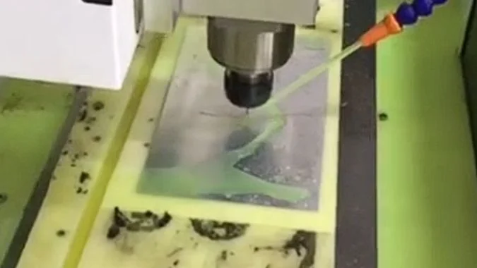
How Is Spindle Speed Calculated from Hole Diameter?
Spindle speed is calculated from the recommended cutting speed and drill diameter:
n = (1,000 × Vc) ÷ (π × D)
In this formula, n is spindle speed in rpm, Vc is cutting speed in meters per minute, and D is tool diameter in millimeters.
A smaller diameter needs more revolutions per minute to create the same edge velocity. For example, a 5 mm drill must rotate four times faster than a 20 mm drill at the same cutting speed. This relationship explains why small-hole production benefits from a high-speed spindle.
Feed rate is calculated with another relationship:
Vf = f × n
In this formula, Vf is feed rate in millimeters per minute, f is feed per revolution, and n is spindle speed. A higher rpm can therefore increase axial feed rate, but only when the tool supports the selected feed per revolution.
| Hole size | Main operating characteristic | Typical limitation |
|---|---|---|
| Below 3 mm | Very high rpm and low feed per revolution | Runout, breakage, and chip blockage |
| 3–20 mm | Broad productive drilling range | Tool wear and chip evacuation |
| Above 20 mm | Lower rpm and greater feed force | Torque, power, thrust, and chip volume |
| Very large diameter | Specialized drilling or interpolation | Machine capacity and process time |
Why Can a Small Hole Still Take a Long Time?
A small drill may operate at high rpm, but its low rigidity limits feed per revolution. Minor spindle runout can become a large percentage of the tool diameter. A few microns of runout may overload one cutting edge6 and cause premature failure.
Small deep holes also provide little space for chips and coolant. A high spindle speed cannot overcome blocked flutes. Micro-drilling may require balanced holders, very low runout, filtered coolant, accurate tool measurement, and controlled entry.
Large holes create a different problem. Their cutting edges remove more material during each revolution. Torque, thrust, and spindle power rise. Large chips also require more flute space and coolant flow. The spindle must deliver enough torque at the selected low speed, not only a high maximum rpm.
Indexable drills are often economical for larger diameters. Pilot drilling, step drilling, annular cutting, boring, or helical interpolation may be used when a solid drill would exceed machine capacity. Each added operation increases cycle time, so hole tolerance and surface requirements should be reviewed before selecting the process.
The fastest method is not always the highest spindle speed. A stable one-pass drill may be faster than an aggressive process that causes frequent tool changes, pecking, inspection, or rework.
Why Does TSC Have a Positive Effect on Maintaining the High Rotation Speed of CNC High-Speed Drilling Machines?
External coolant may cover the hole entrance while the cutting edge remains hot and dry. Chips can then block the flutes, raise torque, and stop an otherwise capable high-speed process.
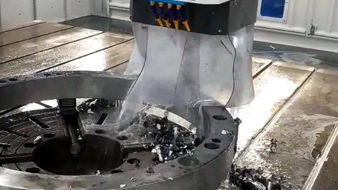
Through-spindle coolant delivers fluid through the tool directly to the cutting edge. It removes heat, lubricates the contact area, and pushes chips out of the hole. These effects reduce torque spikes and thermal damage, allowing high spindle speeds and feed rates to remain stable for longer periods.
How Does TSC Improve Cooling and Chip Evacuation?
Through-spindle coolant, also called TSC or internal coolant, travels through passages in the spindle, holder, and tool. Outlet holes near the drill point direct fluid into the cutting zone. This delivery method is more effective than external nozzles in deep holes because the tool itself blocks external fluid from reaching the bottom.
Coolant absorbs heat from the drill point, margins, chips, and nearby workpiece material. It also provides lubrication between the drill, chip, and hole wall. Lower friction reduces torque and limits built-up edge7.
The coolant stream forces chips back through the drill flutes. Stable chip evacuation prevents chip packing, secondary cutting, wall scratching, and sudden spindle-load increases. This effect allows a drill to maintain continuous feed in applications that might otherwise require frequent pecking.
| TSC function | Direct process effect | Production benefit |
|---|---|---|
| Cutting-edge cooling | Reduces local temperature | Slower tool wear |
| Internal lubrication | Reduces friction and adhesion | Lower cutting load |
| Forced chip evacuation | Clears flutes and hole bottom | Fewer jams and broken tools |
| Stable load control | Limits torque spikes | More reliable high-speed operation |
| Continuous drilling | Reduces peck cycles | Shorter hole cycle time |
| Controlled hole temperature | Limits thermal expansion | Better size consistency |
Does TSC Directly Increase Spindle Speed?
TSC does not increase the motor’s rated maximum rpm. It creates the process conditions required to use a high spindle speed safely. Without proper coolant delivery, heat or packed chips may force a speed reduction even when the spindle can rotate faster.
Coolant pressure must match the drill diameter, passage size, hole depth, and material. Small internal channels may require high pressure, while larger drills usually need greater flow volume. Systems can range from moderate pressure to 70 bar or more. Specialized deep-hole applications may use much higher pressure8. A single pressure target cannot serve every machine.
Filtration is essential. Fine passages in carbide drills can become blocked by chips or contamination. Filter rating, pump flow, tank condition, rotary union capacity, and toolholder seals must support the selected process. Excessively high pressure can damage seals, increase leakage, or exceed the tool manufacturer’s limits.
TSC also does not directly cool spindle bearings unless the machine has a separate spindle-cooling circuit. Its main purpose during drilling is to cool and lubricate the cutting zone and remove chips. Stable spindle-bearing temperature still depends on the spindle’s lubrication and thermal-management design.
A successful TSC process combines suitable pressure, adequate flow, clean fluid, correct concentration, and internal-coolant tooling. When these conditions remain stable, the listed high-speed capability of a CNC drilling machine becomes usable in continuous production rather than only during short test cuts.
Conclusion
Productive drilling speed depends on balancing diameter, depth, material, tooling, machine capacity, and coolant delivery instead of pursuing maximum spindle rpm alone.
-
"Deep hole drilling", https://en.wikipedia.org/wiki/Deep_hole_drilling. The length-to-diameter (L/D) ratio in drilling is defined as the hole depth divided by the nominal drill diameter, a standard metric in machining engineering for characterizing hole geometry. Evidence role: definition; source type: education. Supports: the standard definition of L/D ratio in drilling operations. ↩
-
"Deep hole drilling", https://en.wikipedia.org/wiki/Deep_hole_drilling. Gun drilling and BTA (Boring and Trepanning Association) drilling are established manufacturing processes specifically developed for producing deep holes with L/D ratios exceeding conventional drilling limits. Evidence role: general_support; source type: encyclopedia. Supports: the existence and application of specialized deep-hole drilling methods. ↩
-
"8 keys to success when machining aluminium", https://cuttingtools.ceratizit.com/bg/en/machining-know-how/milling/advisor/machining-aluminium.html. Aluminum alloys exhibit thermal conductivity values typically ranging from 120–200 W/m·K, significantly higher than steel, which facilitates heat removal during cutting and generally permits higher machining speeds. Evidence role: mechanism; source type: research. Supports: aluminum’s high thermal conductivity and its relevance to machining speeds. Scope note: Thermal conductivity is one factor; actual cutting speeds also depend on material strength, chip formation characteristics, and tool-workpiece interactions. ↩
-
"Review on machining of additively manufactured nickel and titanium …", https://www.sciencedirect.com/science/article/pii/S2238785421010772. Titanium alloys typically have thermal conductivity values of 6–22 W/m·K, and nickel-based superalloys range from 10–30 W/m·K, substantially lower than common steels and aluminum, resulting in heat concentration at the cutting edge. Evidence role: statistic; source type: research. Supports: the low thermal conductivity of titanium and nickel-based alloys. ↩
-
"Modulating Surface Machining to Optimize Work …", https://ui.adsabs.harvard.edu/abs/2023JMEP…3210363W/abstract. Austenitic stainless steels exhibit significant strain hardening due to the transformation of austenite to martensite under plastic deformation, a phenomenon well-documented in machining literature that can rapidly increase hardness when inadequate feed causes rubbing. Evidence role: mechanism; source type: research. Supports: work-hardening behavior in austenitic stainless steels during deformation. ↩
-
"Measure and Fix Spindle Runout – The Tool Life Killer", https://tormach.com/articles/measure-fix-spindle-runout-tool-life-killer?hs_amp=true. Radial runout causes one cutting edge to remove more material than the other, creating unbalanced forces, accelerated wear, and increased breakage risk, an effect that becomes proportionally more significant as drill diameter decreases. Evidence role: mechanism; source type: research. Supports: how spindle runout causes unequal cutting edge engagement. ↩
-
"Effect of Built-Up Edge Formation during Stable State of Wear in AISI …", https://pmc.ncbi.nlm.nih.gov/articles/PMC5706177/. Built-up edge formation occurs when friction and temperature at the tool-chip interface cause work material to adhere to the cutting edge; effective lubrication reduces these conditions and inhibits BUE development. Evidence role: mechanism; source type: research. Supports: the role of friction and temperature in built-up edge formation. ↩
-
"What is BTA Drilling – UNISIG Deep Hole Drilling Machines", https://unisig.com/information-and-resources/what-is-deep-hole-drilling/what-is-bta-drilling/. Gun drilling and similar deep-hole processes commonly employ coolant pressures ranging from 500 to 1500 psi (35–100 bar) or higher to ensure adequate chip evacuation and cooling at extreme L/D ratios. Evidence role: statistic; source type: research. Supports: elevated coolant pressures used in specialized deep-hole drilling. Scope note: Pressure requirements vary significantly with hole diameter, depth, material, and specific process technology. ↩

Chris Lu
Leveraging over a decade of hands-on experience in the machine tool industry, particularly with CNC machines, I'm here to help. Whether you have questions sparked by this post, need guidance on selecting the right equipment (CNC or conventional), are exploring custom machine solutions, or are ready to discuss a purchase, don't hesitate to CONTACT Me. Let's find the perfect machine tool for your needs.