

How to Choose Between Pneumatic Lock and Hydraulic Clamping for 4th-Axis Rotary Table of VMC?
Wrong clamping choice causes chatter, drift, and damaged rotary parts. Light jobs become unstable. Heavy jobs can destroy the worm gear and reduce accuracy1.
Pneumatic locking suits light-to-medium indexing work with low cutting force. Hydraulic clamping suits heavy roughing, steel machining, and high lateral loads. The best choice depends on cutting force, workpiece weight, required rigidity, cycle time, and maintenance capacity.
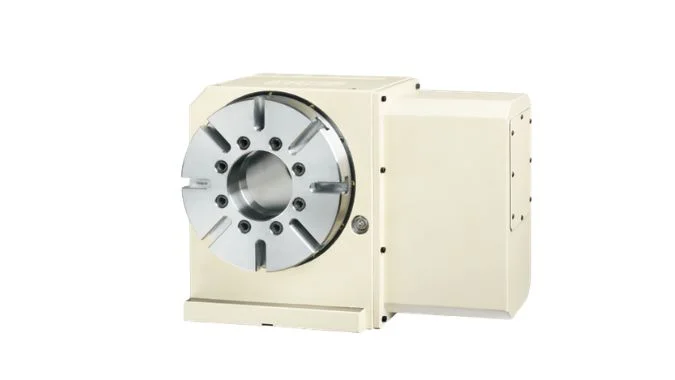
A 4th-axis rotary table is not only a positioning unit. It also becomes part of the machine rigidity chain during cutting. The clamping method decides whether the table holds position under real machining load.
What Kind of Machining Is Pneumatic Locking Sufficient for on a VMC 4th Axis?
Using hydraulic clamping for every job increases cost and maintenance. Yet using air locking beyond its limit causes vibration, tool marks, and indexing drift.
Pneumatic locking is sufficient for light-to-medium cutting, positioning, and indexing on a VMC. It works well for drilling, tapping, light end milling, and 3+1 fixed-position machining of aluminum, copper, plastics, and small steel parts.
Suitable machining conditions
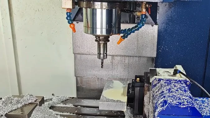
Pneumatic locking is a practical choice when the 4th axis mainly performs positioning work. Common examples include multi-face drilling, tapping, chamfering, and light milling. Many valve bodies, small housings, disc parts, and 3C aluminum parts fall into this range. The rotary table indexes to a fixed angle, locks, and then the VMC completes machining on that face. This is often called 3+1 machining.
The cutting force in these jobs is usually low. Axial cutting is also more friendly to pneumatic locking than strong side cutting. For example, drilling and tapping push mainly along the tool axis. Light end milling on aluminum also creates limited side force. In many cases, the required clamping torque stays below about 50–60 N·m2. Under these conditions, pneumatic locking can hold position with good speed and low cost.
Limits of pneumatic locking
Pneumatic locking should not be treated as a heavy-duty locking method. Compressed air has limited force output. Air is also compressible, so the locking feel is less rigid than oil-based clamping3. If the table faces high lateral force, impact load, or continuous 4-axis interpolation, pneumatic locking may not be enough.
The rotary table structure also matters. Pneumatic locking works better with a high-rigidity worm gear, roller cam, or multi-disc brake design4. Stable air pressure is required, often in the 5–8 bar range depending on the machine builder5. If chatter, tool vibration, tool marks, or indexing drift appear during cutting, the process has likely exceeded the safe range of pneumatic locking.
| Machining type | Pneumatic locking suitability | Reason |
|---|---|---|
| Drilling and tapping | Suitable | Mainly axial cutting force |
| Light aluminum milling | Suitable | Low cutting resistance |
| Copper or plastic machining | Suitable | Smooth cutting and low load |
| Small steel part indexing | Conditionally suitable | Depends on depth and tool load |
| Spiral groove milling | Not suitable | High side force |
| Heavy roughing | Not suitable | Impact and vibration risk |
| Continuous 4-axis cutting | Not suitable | Locking method may not match motion needs |
Why Is Hydraulic Clamping Necessary for Heavy-Duty Roughing and Steel Machining?
Steel cutting creates strong resistance. A weak clamp allows tiny movement. That movement becomes chatter, taper wear, poor surface finish, and possible rotary table damage.
Hydraulic clamping is necessary for heavy-duty roughing and steel machining because oil pressure provides large, stable, and rigid clamping force. It resists high cutting load, workpiece movement, vibration, and gravity effects during demanding 4th-axis operations.
Large clamping force and high rigidity
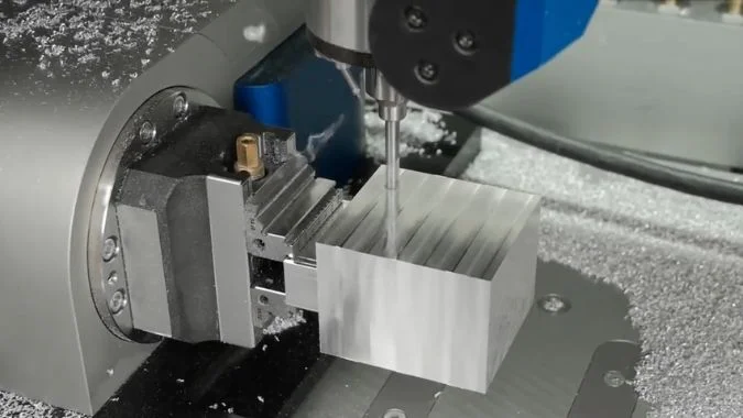
Hydraulic systems use oil as the working medium. Oil is almost incompressible under normal machine conditions6. This gives hydraulic clamping a stronger and more stable locking effect than pneumatic clamping. In heavy roughing, cutting force is not smooth. The tool can strike the workpiece, enter interrupted cuts, and create sudden torque peaks. Hydraulic clamping handles these load changes with better rigidity.
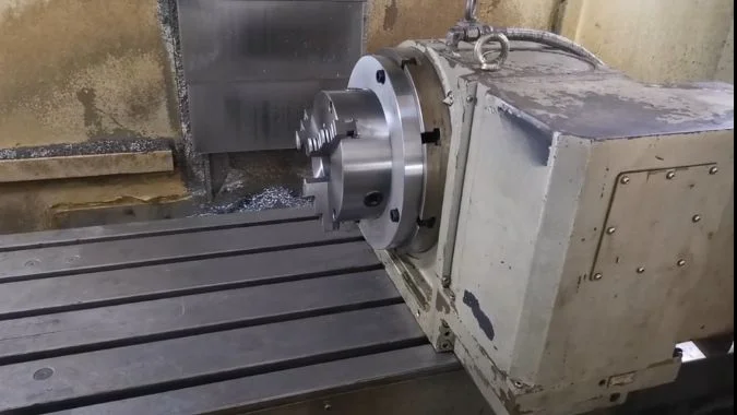
Steel machining needs this extra safety margin. Steel has high density and high cutting resistance. When a large steel workpiece is held on a 4th-axis table, gravity and cutting force can act together. This is especially clear during vertical face milling, inclined face machining, and flange milling. Even a small movement can break the tool path. In precision work, displacement may need to stay below 0.003 mm7. Hydraulic clamping helps control that movement.
Better support for heavy rotary table structures
Heavy-duty 4th-axis tables often use hydraulic clamping together with a Hirth coupling, tooth coupling, gear lock, or reinforced brake structure8. This combination locks the transmission chain and reduces load on the worm gear pair. The result is better vibration resistance and longer table life.
Hydraulic clamping also supports automated CNC cycles. The sequence can be simple: index, clamp, machine, unclamp, and index again. This is useful in production, especially when the workpiece is heavy and manual clamping is not safe or efficient. Hydraulic systems can also keep holding force more reliably in long machining cycles. For roughing cast iron, alloy steel, large flanges, and heavy fixture loads, hydraulic clamping is usually the correct choice.
| Requirement | Pneumatic locking | Hydraulic clamping |
|---|---|---|
| Clamping force | Medium to low | High |
| Rigidity under side load | Limited | Strong |
| Heavy steel roughing | Not recommended | Recommended |
| Impact cutting | Weak resistance | Better resistance |
| Workpiece safety | Good for light parts | Better for heavy parts |
| Cost and maintenance | Lower | Higher |
| Best use | Fast indexing and light cutting | Heavy cutting and high stability |
How Do Clamping and Unclamping Response Times Differ Between Air and Oil Systems?
Cycle time matters in mass production. Slow clamping wastes machine time. Yet fast response without enough holding force can create bigger losses later.
Pneumatic clamping and unclamping usually respond in less than 0.5 seconds. Hydraulic clamping usually takes about 0.5–2 seconds. Pneumatic systems are faster, while hydraulic systems are slower but provide stronger and more stable clamping force.
Why pneumatic response is faster
Compressed air moves quickly through valves and pipelines. Pneumatic solenoid valves often switch in less than 0.1 seconds9. Cylinder action is also fast because air has low flow resistance and the system structure is simple. This makes pneumatic locking suitable for high-cycle production where the table indexes frequently.
A typical example is equal-division machining. A small aluminum part may need drilling on four sides. The 4th axis rotates 90 degrees, locks, drills, unlocks, and rotates again. If this sequence repeats thousands of times per day, response speed becomes important. Pneumatic locking reduces non-cutting time and helps keep production rhythm smooth.
Why hydraulic response is slower but stronger
Hydraulic clamping uses oil. Oil provides better force transfer, but the system needs time to build pressure. Hydraulic valves, cylinders, pipelines, oil viscosity, and load all affect response. For this reason, clamping and unclamping usually take about 0.5–2 seconds. Longer pipelines and colder oil can make the response slower.
The slower action does not mean poor performance. Hydraulic clamping is designed for holding power, not only speed. In heavy machining, the extra second is usually acceptable because part safety and cutting stability matter more than indexing speed. For flange milling, steel roughing, and high lateral force machining, stable locking force saves tools, protects the rotary table, and improves part quality.
| Item | Pneumatic system | Hydraulic system |
|---|---|---|
| Medium | Compressed air | Hydraulic oil |
| Typical response | Less than 0.5 seconds | 0.5–2 seconds |
| Valve action | Very fast | Moderate |
| Force output | Lower | Higher |
| Stability under load | Moderate | Strong |
| Best production style | Frequent light indexing | Heavy clamped cutting |
| Main trade-off | Speed over force | Force over speed |
What Are the Maintenance Challenges of Hydraulic Leaks and Pneumatic Condensation?
Good clamping fails when maintenance is ignored. Oil leaks reduce pressure. Water in air lines causes rust, valve sticking, slow action, and hidden ATC-style faults.
Hydraulic systems mainly face leakage, oil contamination, seal wear, heat, and pressure loss. Pneumatic systems mainly face condensation, rust, valve sticking, air leakage, and loss of lubrication. Both require preventive inspection to protect rotary table accuracy.
Hydraulic leakage problems
Hydraulic leakage can be external or internal. External leakage is easy to see because oil appears around pipe joints, cylinders, valve blocks, or seals. It can contaminate the cutting area and create safety risks. Oil on the machine floor can cause slipping. Oil mist or leakage near hot parts can also create fire risk in poor shop conditions.
Internal leakage is harder to find. The system may look clean, but clamping force slowly drops. Indexing may become less accurate. The rotary table may still move, but the brake or clamp no longer holds with full force. This can create chatter and repeatability error. Leakage is often linked with seal aging, scratched cylinder surfaces, dirty oil, worn valve spools, and high oil temperature.
Hydraulic oil cleanliness must be controlled. Dirty oil accelerates valve and seal wear. In high-quality systems, oil cleanliness may be monitored using ISO 4406 standards10. Oil oxidation, dark color, foam, and rising temperature are warning signs. Repair often requires downtime, cleaning, seal replacement, oil replacement, and pressure testing.
Pneumatic condensation problems
Pneumatic systems avoid oil leakage in the work area, but water becomes the main enemy. Compressed air carries moisture. If the air dryer, oil-water separator, or filter is poor, condensation collects in pipes, cylinders, and solenoid valves. This water causes rust and washes away lubrication. Valve spools may stick. Cylinders may move slowly. Clamping or unclamping may fail.
In low-temperature shops, water can freeze inside the air line. This can block flow or damage components. Pneumatic condensation is also easy to misjudge as a mechanical failure. A slow clamp may be blamed on a worn rotary table, while the real cause is water in the air line.
Daily drainage is important. Automatic drains, manual drains, after-coolers, air dryers, oil-water separators, and clean filters reduce the risk. Micro-oil mist lubrication may be needed depending on the system design. Stable dry air is as important to pneumatic locking as clean oil is to hydraulic clamping.
| Maintenance issue | Hydraulic clamping | Pneumatic locking |
|---|---|---|
| Main failure source | Oil leakage and contamination | Water and air leakage |
| Hidden fault | Internal leakage | Moisture inside valves |
| Common symptom | Pressure loss and weak clamp | Slow action and sticking valve |
| Environmental risk | Oil pollution | Water discharge and corrosion |
| Key maintenance | Seal check and oil cleanliness | Drainage and air drying |
| Accuracy impact | Reduced rigidity and repeatability | Delayed lock and unstable action |
Conclusion
Pneumatic locking fits fast light indexing. Hydraulic clamping fits heavy steel cutting. The right choice depends on force, rigidity, speed, and maintenance conditions.
-
"Raising the bar on rotary table accuracy – Renishaw", https://www.renishaw.com/de/raising-the-bar-on-rotary-table-accuracy–44360?srsltid=AfmBOorGDyZMCE7vO0ZIPrGMF5SqR0R2EA_NdT5wTaXgTbo7-n6tzlr9. Machine tool design literature documents that worm gear pairs used in rotary table drives are sensitive to shock loads and sustained lateral forces beyond their rated capacity; overloading accelerates tooth wear and backlash growth, directly degrading angular positioning accuracy and repeatability. Evidence role: mechanism; source type: research. Supports: The susceptibility of worm gear drives in CNC rotary tables to damage from excessive cutting loads and the resulting loss of positioning accuracy. Scope note: The severity of accuracy loss depends on gear quality, material, lubrication, and the magnitude and frequency of overload events. ↩
-
"[PDF] 4th and 5th Axis Rotary Table – Digital Commons @ Cal Poly", https://digitalcommons.calpoly.edu/context/mesp/article/1362/viewcontent/21_Final_Report.pdf. Machine tool engineering references and rotary table specifications indicate that pneumatic clamping systems are generally rated for moderate torque ranges, with practical limits varying by table diameter, brake design, and supply pressure; the 50–60 N·m figure represents a commonly cited threshold in light-duty indexing applications. Evidence role: statistic; source type: research. Supports: Typical clamping torque ranges for pneumatic locking systems on CNC rotary tables. Scope note: Exact torque limits vary significantly by manufacturer and table model; this figure should be verified against specific equipment datasheets. ↩
-
"A Pneumatic Particle-Blocking Variable-Stiffness Actuator – PMC", https://pmc.ncbi.nlm.nih.gov/articles/PMC10747411/. Fluid power engineering textbooks establish that the high compressibility of air (bulk modulus approximately 0.14 MPa at atmospheric conditions) results in significantly lower actuator stiffness compared to hydraulic oil, causing pneumatic clamping systems to exhibit greater compliance under dynamic cutting loads. Evidence role: mechanism; source type: education. Supports: The relationship between air compressibility and reduced actuator stiffness in pneumatic clamping systems relative to hydraulic systems. ↩
-
"Custom CNC Rotary Table index table Manufacturer | SILVERCNC", https://www.silvercnc.com/rotary-table/. Rotary table design literature describes roller cam (barrel cam) drives as offering higher rigidity and zero-backlash indexing compared to conventional worm gear designs, while multi-disc brake systems distribute clamping force over a larger contact area; both designs can improve the effective holding performance of pneumatic clamping by reducing the compliance introduced by the drive mechanism. Evidence role: mechanism; source type: research. Supports: The mechanical characteristics of roller cam and multi-disc brake rotary table designs and their compatibility with pneumatic clamping systems. Scope note: The relative suitability of these designs for pneumatic locking depends on the specific load case and is not universally established in the cited literature. ↩
-
"1926.803 – Compressed air. | Occupational Safety and … – OSHA", http://www.osha.gov/laws-regs/regulations/standardnumber/1926/1926.803. Industrial pneumatic system standards and CNC machine tool documentation commonly specify supply pressures in the 5–8 bar range for actuator-based clamping, consistent with general pneumatic circuit design guidelines for machine tools. Evidence role: statistic; source type: institution. Supports: Standard operating pressure ranges for pneumatic clamping systems in CNC machine tool applications. Scope note: Actual required pressure varies by cylinder bore, clamping force requirement, and individual machine builder specification; the stated range is indicative rather than universally prescriptive. ↩
-
"[PDF] Experimental measurements of bulk modulus for two types of …", https://tud.qucosa.de/api/qucosa%3A29304/attachment/ATT-0/?L=1. Fluid mechanics principles establish that hydraulic oils have a bulk modulus on the order of 1.5–2.0 GPa, making them effectively incompressible under typical machine tool pressures, whereas air is highly compressible, resulting in fundamentally different stiffness characteristics between hydraulic and pneumatic clamping systems. Evidence role: mechanism; source type: encyclopedia. Supports: The near-incompressibility of hydraulic oil relative to compressed air and its effect on force transmission rigidity in hydraulic systems. ↩
-
"[PDF] 4th and 5th Axis Rotary Table – Digital Commons @ Cal Poly", https://digitalcommons.calpoly.edu/context/mesp/article/1362/viewcontent/21_Final_Report.pdf. ISO 230-1 and related machine tool accuracy standards define positioning and repeatability tolerances for CNC rotary axes; sub-micron to low-micron displacement limits are consistent with precision machining requirements for steel components where surface finish and dimensional accuracy are critical. Evidence role: statistic; source type: institution. Supports: Precision displacement tolerances applicable to 4th-axis rotary table clamping in steel machining operations. Scope note: The specific 0.003 mm figure is application-dependent and not universally standardized; actual tolerance requirements vary by part specification and machining process. ↩
-
"On Hirth Ring Couplings: Design Principles Including the Effect of …", https://www.academia.edu/63261192/On_Hirth_Ring_Couplings_Design_Principles_Including_the_Effect_of_Friction. Hirth couplings, also known as serrated or curvic couplings, use interlocking radial teeth to achieve high-precision angular positioning and rigid torque transmission; their application in rotary table locking systems is documented in machine tool design literature as a method for achieving high clamping rigidity while distributing load away from the worm gear pair. Evidence role: definition; source type: encyclopedia. Supports: The design and function of Hirth couplings and similar tooth-type locking mechanisms in CNC rotary table applications. ↩
-
"Rapid Prototyping of Pneumatic Directional Control Valves – PMC", https://pmc.ncbi.nlm.nih.gov/articles/PMC8124538/. Pneumatic solenoid valve datasheets and industrial automation references commonly report switching times in the range of 10–100 milliseconds depending on valve size, flow rating, and coil design, consistent with the sub-0.1-second figure cited for CNC clamping applications. Evidence role: statistic; source type: research. Supports: Typical switching response times for pneumatic solenoid valves in industrial automation and CNC machine tool applications. Scope note: Actual response time depends on valve model, supply pressure, flow path length, and downstream volume; the stated figure represents a general benchmark rather than a universal specification. ↩
-
"ISO 4406: What Do Those Numbers Mean in the ISO Cleanliness …", https://www.hyprofiltration.com/blog/bid/216397/iso-4406-what-do-those-numbers-mean-in-the-iso-cleanliness-codes. ISO 4406:2021 specifies a method for coding the level of contamination by solid particles in hydraulic fluid power systems, providing a three-number cleanliness code based on particle counts per milliliter at 4 µm, 6 µm, and 14 µm thresholds; this standard is widely referenced in machine tool hydraulic system maintenance guidelines. Evidence role: definition; source type: institution. Supports: ISO 4406 as the applicable standard for classifying hydraulic fluid cleanliness by particle count in industrial machine tool systems. ↩

Chris Lu
Leveraging over a decade of hands-on experience in the machine tool industry, particularly with CNC machines, I'm here to help. Whether you have questions sparked by this post, need guidance on selecting the right equipment (CNC or conventional), are exploring custom machine solutions, or are ready to discuss a purchase, don't hesitate to CONTACT Me. Let's find the perfect machine tool for your needs.