

How Do Workpiece Clamping and Positioning Issues Influence Tool Marks?
Poor clamping can ruin a surface even when the cutter is good. The part moves, bends, or vibrates, and tool marks become hard to control.
Workpiece clamping and positioning issues influence tool marks by causing micro-movement, elastic deformation, unstable support, and vibration transmission. These problems change the real cutting path, so the machined surface may show irregular lines, chatter waves, dents, or uneven milling marks.
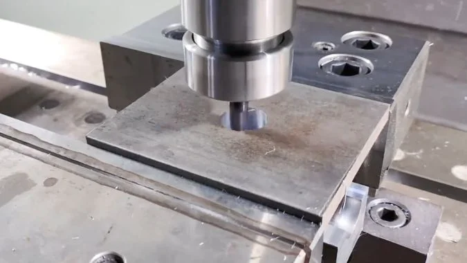
Clamping looks simple, but it is one of the main hidden causes of tool marks. If the workpiece is not held with the right force and support, the cutter cannot create a stable surface. Insufficient clamping force allows the part to move under cutting load1. Excessive clamping force can deform thin sheets or precision parts. An uneven bottom surface can make the workpiece sit on chips, burrs, or residues instead of stable contact points. A weak fixture can also transmit and increase vibration. These problems are common in thin-walled parts, large plates, aluminum sheets, and precision components. Good surface quality starts before the spindle turns. It starts with clean contact, balanced clamping force, strong support, and stable positioning.
How Does Cutting Vibration Act as the Invisible Killer of Surface Quality?
Vibration is difficult to see during machining. Yet it can quickly turn a smooth surface into a surface with waves, noise, and rejected tool marks.
Cutting vibration damages surface quality by making the tool and workpiece move against each other during cutting. Forced vibration, resonance, chatter, and excessive tool overhang can create dense waves, irregular marks, poor roughness, and unstable dimensions.
Forced vibration and resonance
Forced vibration comes from repeated outside forces. In milling, each cutting tooth enters and leaves the workpiece. Each entry creates a small impact. These impacts repeat at a fixed frequency. If this frequency comes close to the natural frequency of the machine, fixture, tool, or workpiece, resonance can appear. Once resonance appears, the vibration becomes much larger. The surface can change from acceptable to poor in a very short time.
Other vibration sources can also matter. A rotating spindle with imbalance can add periodic force. A poorly balanced tool holder can increase vibration at high speed. Ground vibration near heavy equipment can affect some precision processes. A weak fixture can receive cutting force and send vibration back to the workpiece. In this case, the fixture becomes a vibration amplifier.
| Vibration source | Common surface sign | Main cause | Practical check |
|---|---|---|---|
| Tooth impact | Regular fine waves | Each flute enters the cut repeatedly | Compare mark spacing with feed and spindle speed |
| Resonance | Sudden severe surface marks | Cutting frequency matches system natural frequency | Change spindle speed and observe the surface |
| Tool imbalance | Repeated vibration marks | Holder or cutter is not balanced | Check balance grade and tool assembly |
| Fixture vibration | Local deep marks | Fixture lacks rigidity or damping | Add support and test again |
| Floor vibration | Random unstable marks | External equipment affects the machine | Check nearby heavy machines or presses |
Chatter and tool overhang
Chatter is one of the most damaging vibration forms. It is a self-excited vibration. The previous cut leaves small waves on the surface. The next cut follows those waves and creates stronger vibration2. This cycle repeats. The sound often becomes a sharp, high-frequency whistle. The surface then shows dense and regular waves. Surface roughness becomes worse very quickly.
Tool overhang has a strong effect on chatter. A longer overhang reduces tool rigidity sharply. In simple terms, tool rigidity drops very fast as overhang grows3. This is why a small increase in tool length can create a large increase in tool marks. For general milling, overhang should often stay within 3 times the tool diameter4. For precision finishing, keeping it within 2 times the tool diameter is safer. Shorter tools, stronger holders, unequal pitch end mills, and better support near the cutting zone can reduce vibration. Cutting speed, feed, and depth of cut should also avoid the speed zones that trigger chatter.
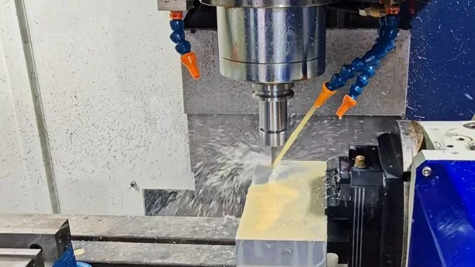
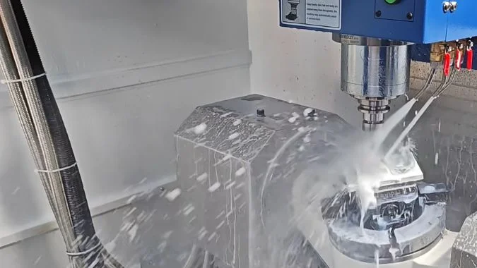
What Role Do Cooling and Lubrication Conditions Play in Reducing Milling Marks?
Cutting fluid is often treated as a background detail. Poor cooling or lubrication can still damage the tool edge and leave visible milling marks.
Cooling and lubrication reduce milling marks by lowering heat, reducing friction, helping chip evacuation, and slowing tool wear. Wrong fluid type, wrong concentration, or poor spray direction can cause built-up edge, scratches, heat damage, and rougher surfaces.
Cooling, lubrication, and chip evacuation
Cutting fluid has three main jobs. It cools the cutting zone. It lubricates the contact between the tool, chip, and workpiece. It also helps remove chips from the cutting area. If any one of these jobs fails, milling marks can become worse.
Insufficient cooling raises the temperature at the cutting edge. High temperature accelerates tool wear5. It may also change the local behavior of the workpiece material. Some materials may soften. Some materials may form a hardened surface layer. Some may stick to the tool edge and create built-up edge. These changes make the cutting action less stable. The surface then shows deeper, torn, or random marks.
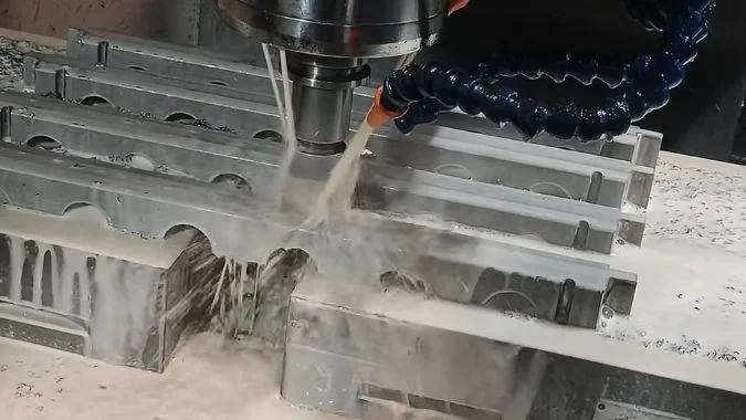
Lubrication is also important. Poor lubrication increases friction. More friction creates more heat and more tool wear. It also makes chips more likely to weld to the edge. Chip evacuation should not be ignored. If chips stay in the cutting zone, the cutter may cut them again. Recut chips can scratch the finished surface and leave random lines.
Fluid type, concentration, and supply position
Different materials need different fluid choices. Aluminum alloys often work well with oil-based or vegetable-based cutting oils6 when surface finish is important. Stainless steel and titanium alloys often need extreme pressure fluids because friction and heat are severe. Cast iron is often machined dry or with air blowing because chips are powder-like7 and coolant may create sludge. The wrong fluid type can make parameter adjustment much less useful.
Concentration also matters. If concentration is too low, lubrication and rust protection may be weak. If it is too high, foaming, residue, and poor chip flow may appear. Supply direction is another common problem. Cutting fluid should reach the cutting zone, not only the tool shank or the outer edge of the part. Through-spindle coolant is very effective because it sends fluid directly to the cutting edge and improves chip removal.
| Cooling and lubrication factor | If poorly controlled | Surface result | Better practice |
|---|---|---|---|
| Cooling capacity | Cutting zone overheats | Wear marks and heat-related roughness | Increase flow or improve coolant access |
| Lubrication strength | Friction becomes high | Torn surface and built-up edge | Select proper fluid type |
| Chip evacuation | Chips stay in the cut | Random scratches and dents | Use air blast or directed coolant |
| Fluid concentration | Too weak or too strong | Poor lubrication, foam, or residue | Keep concentration within recommended range |
| Spray direction | Fluid misses the cutting edge | Limited improvement in marks | Aim at the tool-workpiece contact point |
| Through-spindle coolant | Not available in deep cutting | Chips are hard to remove | Use when precision and chip control are critical |
How Do Toolpaths and Machining Strategies Impact the Final Surface Finish?
A CNC program can create a good part or a marked surface. Toolpath direction, entry method, allowance, and strategy all shape the finish.
Toolpaths and machining strategies impact surface finish by controlling cutter engagement, residual height, starting marks, ending marks, and cutting force stability. Poor step-over, direct plunging, uneven finishing allowance, or unsuitable surface strategy can leave obvious milling marks.
Feed direction, step-over, and toolpath marks
Toolpath direction decides the direction of visible milling marks. In face milling and planar milling, each pass leaves a trace. The distance between adjacent passes is the step-over. If step-over is too large, the residual height between paths becomes obvious. This creates regular grooves or ridges. Reducing step-over improves finish, but it also increases machining time. A practical process must balance surface quality and efficiency.
Feed direction also changes the cutting force direction. Some parts are more stable in one direction than another. Thin plates, long workpieces, and weakly supported areas may vibrate more when the cutting force pushes them away from support. A toolpath that follows the strongest support direction can reduce marks. For finishing, climb milling is often preferred when the machine has good backlash control8. It usually gives a cleaner surface and lower rubbing than conventional milling.
Lead-in, lead-out, and finishing allowance
Lead-in and lead-out methods leave marks at the start and end of the toolpath. Direct vertical plunging can leave a clear point mark. A sudden side entry can create a force spike and leave a short scratch or dent. Arc lead-in allows the tool to enter the cut gradually. Cutting force changes more smoothly, so the start mark becomes lighter. Arc lead-out works in the same way at the end of the pass.
Finishing allowance is another major factor. If roughing leaves too much stock, the finishing cut becomes too heavy. Cutting force rises, vibration increases, and marks become deeper. If the allowance is too small, the finishing tool may rub instead of cut. It may also fail to remove a hardened layer left by the previous operation. A common finishing allowance range is 0.1 mm to 0.5 mm9, but the exact value depends on material, tool diameter, tool rigidity, and machine condition.
Surface machining strategy also matters. Z-level machining works well on steep areas, but it may leave clear layer marks on some surfaces. Scallop or constant cusp machining keeps residual height more even. It often gives a more uniform surface on free-form shapes.
| Machining strategy factor | Risk when unsuitable | Surface effect | Preferred direction |
|---|---|---|---|
| Step-over | Too large between paths | Regular ridges and grooves | Reduce step-over for finishing |
| Feed direction | Cutting force pushes weak area | Local vibration marks | Cut toward stronger support |
| Direct plunge | Sudden tool engagement | Entry point marks | Use ramp or arc entry |
| Sudden lead-out | Cutting force changes quickly | Exit scratch or small dent | Use arc lead-out |
| Roughing allowance | Too much or too little stock | Chatter, rubbing, or uneven finish | Keep stable finishing allowance |
| Z-level machining | Uneven cusp on some surfaces | Layer marks on slopes | Use where geometry is suitable |
| Scallop machining | Longer programming or cycle time | More uniform residual height | Use for curved surface finishing |
What Are the Most Effective Practical Countermeasures to Improve and Eliminate Milling Marks?
Milling marks rarely come from one cause only. Tooling, parameters, clamping, coolant, and strategy must be improved together.
The most effective countermeasures for milling marks include stable clamping, shorter tool overhang, sharp coated tools, proper finishing parameters, controlled spindle runout, suitable coolant delivery, arc lead-in and lead-out, and balanced roughing-to-finishing allowance.
Tooling and parameter countermeasures
Tool control should begin before the surface becomes unacceptable. A tool change cycle is better than waiting for serious wear marks. Carbide tools with suitable PVD coatings can improve heat resistance and wear life10. A larger corner radius can reduce theoretical residual height, but it should only be used when the machine and fixture are rigid enough. Tool geometry should match the material. Softer sticky materials need sharp cutting edges and good chip flow. Harder materials need stronger edges and stable coatings.
Parameter control is just as important. During finishing, feed rate is often reduced to 30% to 50% of roughing feed11. Cutting speed should stay in a stable middle-to-high range based on material recommendations. Very low speed can create built-up edge. Very high speed can create heat wear. Climb milling is often useful in finishing if machine backlash is controlled. A semi-finishing pass can also help because it leaves a stable and even allowance for the final pass.
Machine, clamping, coolant, and strategy countermeasures
Machine and clamping checks should be routine. Spindle runout should be measured regularly. If runout exceeds the process limit, maintenance is needed. Shrink-fit holders and hydraulic holders can reduce tool system runout. The workpiece bottom surface should be cleaned before clamping. Burrs, chips, and residues can make the part unstable. Thin parts should use enough support points. Fixtures should be checked for rigidity and damping.
Cooling and lubrication should be adjusted based on the material. Coolant should reach the cutting zone directly. Air blowing, external coolant, or through-spindle coolant should be selected based on chip control needs. Toolpath changes can also remove many marks. Shorter tool overhang reduces vibration. Unequal pitch end mills can break chatter regularity. Arc lead-in and lead-out reduce start and stop marks. Scallop machining can keep residual height more uniform on curved surfaces.
The table below works as a practical checklist. It groups the countermeasures by the part of the process that needs control.
| Improvement area | Effective countermeasure | Main purpose | Best used when |
|---|---|---|---|
| Tool life control | Establish a tool change cycle | Prevent wear marks before they appear | Surface quality changes with tool age |
| Tool material | Use coated carbide tools | Improve heat and wear resistance | High-speed or hard-material milling |
| Tool geometry | Use proper rake angle and corner radius | Balance sharpness, force, and finish | Marks come from rubbing or residual height |
| Feed setting | Reduce finishing feed to 30%–50% of roughing feed | Lower residual height and tooth load | Regular feed marks are visible |
| Cutting speed | Avoid low BUE-prone speed zones | Reduce sticking and torn surfaces | Aluminum, mild steel, or stainless steel shows BUE |
| Finishing process | Add semi-finishing pass | Keep final allowance stable | Roughing leaves uneven stock |
| Tool holding | Use shrink-fit or hydraulic holders | Reduce runout and vibration | Alternating marks or runout are found |
| Clamping | Clean and support the workpiece correctly | Prevent movement and deformation | Thin plates or large parts show uneven marks |
| Fixture rigidity | Add auxiliary supports | Reduce vibration transmission | Marks appear near weak support areas |
| Tool overhang | Keep overhang within 2–3 times tool diameter | Improve tool rigidity | Chatter or wave marks appear |
| Cutter design | Use unequal pitch end mills | Break chatter regularity | High-frequency whistling is heard |
| Coolant delivery | Aim coolant at the cutting zone | Improve cooling and chip evacuation | Scratches or BUE appear |
| Toolpath | Use arc lead-in and lead-out | Reduce start and stop marks | Entry or exit marks are visible |
| Surface strategy | Use scallop machining for curved surfaces | Keep residual height uniform | 3D surfaces show uneven layer marks |
Conclusion
Clamping, vibration, coolant, and toolpath choices all shape tool marks. Stable support and controlled cutting conditions remain the fastest path to better surface quality.
-
"Clamping force prediction based on deep spatio-temporal network …", https://pmc.ncbi.nlm.nih.gov/articles/PMC10147658/. Research in manufacturing engineering demonstrates that inadequate clamping force permits workpiece displacement under cutting loads, compromising dimensional accuracy and surface finish. Evidence role: mechanism; source type: paper. Supports: the relationship between clamping force magnitude and workpiece stability during cutting operations. Scope note: The threshold force varies with workpiece geometry, material properties, and cutting parameters ↩
-
"[PDF] Chatter Stability of Machining Operations", https://mtrc.utk.edu/wp-content/uploads/sites/45/2020/08/manu_142_11_110801.pdf. Studies in machining dynamics explain regenerative chatter as a process where surface undulations from previous tool passes modulate chip thickness in subsequent passes, creating a positive feedback loop that amplifies vibration. Evidence role: mechanism; source type: paper. Supports: the regenerative feedback mechanism in machining chatter. ↩
-
"[PDF] Tool Length-Dependent Stability Surfaces", https://mtrc.utk.edu/wp-content/uploads/sites/45/2019/09/tool_length_stability.pdf. According to beam deflection theory applied to cutting tools, rigidity decreases proportionally to the cube of the overhang length, explaining the rapid loss of stiffness with extended tool projection. Evidence role: mechanism; source type: education. Supports: the inverse relationship between cantilever tool overhang and structural rigidity. Scope note: The exact relationship depends on tool diameter, material properties, and cross-sectional geometry ↩
-
"[PDF] Helical – MACHINING GUIDEBOOK", https://web.mae.ufl.edu/designlab/Advanced%20Manufacturing/Helical_Machining_Guidebook.pdf. Machining handbooks commonly recommend maintaining tool overhang within 3 times the tool diameter for general milling to balance accessibility and rigidity, with tighter ratios for precision work. Evidence role: expert_consensus; source type: education. Supports: industry-standard tool overhang-to-diameter ratios for milling operations. Scope note: Optimal ratios vary with material hardness, cutting depth, and required surface finish ↩
-
"Comparison of Tool Wear, Surface Roughness, Cutting Forces, Tool …", https://pmc.ncbi.nlm.nih.gov/articles/PMC10303288/. Tribological research in metal cutting demonstrates that increased cutting temperatures accelerate diffusion wear, oxidation, and thermal softening of tool materials, significantly reducing tool life. Evidence role: mechanism; source type: paper. Supports: the acceleration of tool wear mechanisms at elevated temperatures. Scope note: The temperature-wear relationship varies with tool coating, workpiece material, and cutting speed ↩
-
"Cutting fluid – Wikipedia", https://en.wikipedia.org/wiki/Cutting_fluid. Machining references indicate that aluminum alloys respond well to oil-based and vegetable-based cutting fluids due to their excellent lubricity, which reduces built-up edge formation and improves surface finish on these relatively soft, adhesive materials. Evidence role: expert_consensus; source type: education. Supports: the suitability of oil-based cutting fluids for aluminum machining. Scope note: Fluid selection also depends on specific alloy composition, machining operation, and environmental considerations ↩
-
"Cast iron machining concerns? : r/Machinists – Reddit", https://www.reddit.com/r/Machinists/comments/1ag0xl2/cast_iron_machining_concerns/. Manufacturing handbooks note that cast iron is frequently machined dry or with compressed air because its brittle, discontinuous chips do not require liquid coolant for evacuation, and fluid can create abrasive sludge that complicates chip handling. Evidence role: expert_consensus; source type: education. Supports: the common practice of dry or air-assisted machining for cast iron. Scope note: Some cast iron grades and high-speed operations may benefit from minimal quantity lubrication or specific coolants ↩
-
"Climb vs. Conventional Milling : r/Machinists – Reddit", https://www.reddit.com/r/Machinists/comments/10x6m2m/climb_vs_conventional_milling/. Machining literature indicates that climb milling typically produces superior surface finish compared to conventional milling by reducing rubbing and work hardening, but requires machines with minimal backlash to prevent tool pull-in and workpiece displacement. Evidence role: expert_consensus; source type: education. Supports: the preference for climb milling in finishing operations on machines with minimal backlash. Scope note: The optimal milling direction also depends on workpiece rigidity, clamping arrangement, and material properties ↩
-
"[PDF] MATERIAL REMOVAL PROCESSES", https://www.egr.msu.edu/~pkwon/me478/machining.pdf. Process planning references commonly specify finishing allowances between 0.1 and 0.5 mm, balancing the need to remove previous operation marks while maintaining light cutting forces for optimal surface finish. Evidence role: expert_consensus; source type: education. Supports: typical finishing allowance values in machining operations. Scope note: Optimal allowance varies significantly with workpiece size, material hardness, required tolerance, and machine capability ↩
-
"Influence of Nanocomposite PVD Coating on Cutting Tool Wear …", https://pmc.ncbi.nlm.nih.gov/articles/PMC12073052/. Materials research on cutting tool coatings demonstrates that PVD coatings such as TiN, TiAlN, and AlCrN significantly improve carbide tool performance by providing thermal barriers, reducing friction, and increasing surface hardness, thereby extending tool life. Evidence role: mechanism; source type: paper. Supports: the performance improvements provided by PVD coatings on carbide cutting tools. Scope note: Coating effectiveness depends on proper selection for specific workpiece materials, cutting conditions, and substrate preparation ↩
-
"Speeds and feeds – Wikipedia", https://en.wikipedia.org/wiki/Speeds_and_feeds. Machining process planning guides commonly recommend reducing feed rates to 30-50% of roughing values during finishing operations to decrease residual height, minimize cutting forces, and achieve required surface roughness specifications. Evidence role: expert_consensus; source type: education. Supports: typical feed rate reductions from roughing to finishing operations. Scope note: Optimal feed reduction depends on material machinability, tool geometry, required surface finish, and machine dynamics ↩

Chris Lu
Leveraging over a decade of hands-on experience in the machine tool industry, particularly with CNC machines, I'm here to help. Whether you have questions sparked by this post, need guidance on selecting the right equipment (CNC or conventional), are exploring custom machine solutions, or are ready to discuss a purchase, don't hesitate to CONTACT Me. Let's find the perfect machine tool for your needs.