

What Are the Effects of Vibration During Machining on a Slant-Bed CNC Lathe?
Vibration can quietly destroy turning stability. Light marks may appear first, but the machine, tool, and workpiece are already under harmful stress.
Vibration during machining on a slant-bed CNC lathe reduces surface quality, lowers geometric accuracy, shortens tool life, damages machine components, limits cutting efficiency, and increases noise. If chatter appears, the surface often shows periodic marks, and the cutting process becomes unstable.
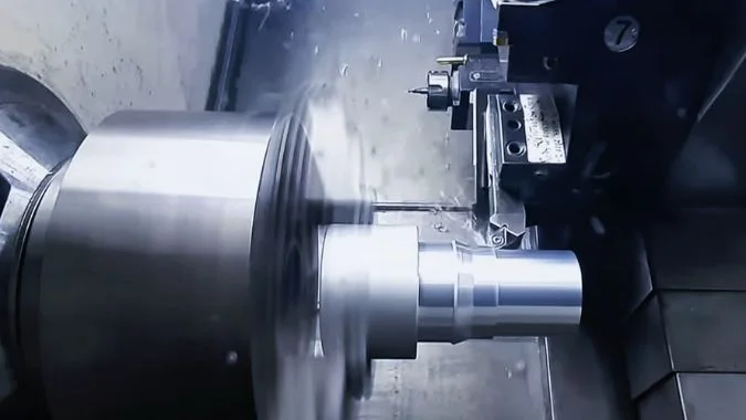
Vibration should be treated as a full-system problem, not only as a cutting problem. A slant-bed CNC lathe usually has better chip removal and stronger structural support than many flat-bed machines. Yet it can still vibrate when the stable cutting zone is exceeded. The first result is poor workpiece quality. Chatter marks, scratches, roundness errors, and cylindricity errors may appear. The second result is shorter tool life. Vibration creates repeated impact loads, so carbide and ceramic inserts may chip quickly. The third result is machine damage. Bearings, guideways, ballscrews, bolts, and contact surfaces may loosen or wear faster. The fourth result is lower production efficiency. Cutting speed, feed rate, and depth of cut often need to be reduced to suppress vibration. This protects the process, but it also lowers output. In automated production lines, one machine stop caused by vibration can disturb the full production rhythm.
What Kinds of Vibrations Occur During the Machining of Slant-Bed CNC Lathes?
Many vibration problems are simply called chatter on the shop floor. In real diagnosis, vibration type must be separated first, because each type needs a different correction.
The main vibration types in slant-bed CNC lathe machining are free vibration, forced vibration, and self-excited vibration. Free vibration comes from a short initial impact. Forced vibration comes from repeated external forces. Self-excited vibration comes from the cutting system itself and is the most dangerous.
Free vibration, forced vibration, and self-excited vibration
Free vibration is usually the least serious type in most turning operations. It starts after one short shock, such as a small impact during loading, tool contact, or clamping. The machine receives energy once, and then the vibration fades out. This type of vibration normally does not become the main reason for long chatter marks. Still, repeated short impacts may show that the setup, loading method, or clamping process needs checking.
Forced vibration is more common. It comes from repeated external excitation. In a lathe, this may come from spindle imbalance, chuck imbalance, misalignment, gear problems, hydraulic unit vibration, motor vibration, or floor vibration. The force repeats at a fixed frequency. The machine then responds at that frequency. If the excitation frequency gets close to the natural frequency of the machine system, the vibration becomes much larger.1
Self-excited vibration is the most dangerous type. Chatter belongs to this group.2 The cutting process creates its own excitation. The previous tool pass leaves a small wave on the surface. The next pass cuts over that wave and creates a new wave. This loop can grow quickly.3 A sharp sound often appears, and dense repeated marks appear on the workpiece surface.
| Vibration type | Main source | Common sign | Risk level |
|---|---|---|---|
| Free vibration | One-time impact or pulse | Short vibration that fades | Low in most machining cases |
| Forced vibration | Repeated external force | Regular vibration linked to speed or equipment | Medium to high |
| Self-excited vibration | Cutting process itself | Chatter marks and sharp noise | Very high |
| Resonance condition | Frequency match between excitation and structure | Sudden vibration increase | Very high |
Why slant-bed machines still vibrate
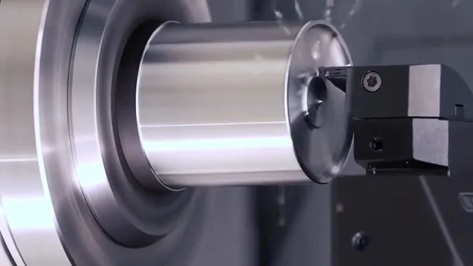
A slant-bed CNC lathe has real structural advantages. The bed angle helps chip removal. The structure can support the carriage well.4 The gravity component can also help contact stability in some conditions. These advantages reduce vibration risk, but they do not remove vibration completely. If the tool overhang is too long, the workpiece is slender, the chuck grip is weak, or the cutting force is too high, the system can still lose stability.
The relationship between tool, workpiece, spindle, turret, guideway, and foundation is very important. These parts do not vibrate alone. They form one dynamic system. A small weakness in one part can become serious when the cutting force repeats at the wrong frequency. This is why chatter should not be handled only by changing the insert. The full force path should be checked, from the cutting edge to the tool holder, turret, guideways, bed, and foundation. A stable process needs all these parts to work together.
Does Improper Machine Leveling and Foundation Setup Cause Unexpected Resonance?
Leveling and foundation problems are easy to underestimate. A machine may cut well at installation, then become unstable after the floor settles or support conditions change.
Yes, improper machine leveling and poor foundation setup can cause unexpected resonance. Bed twisting, weak support, loose anchor bolts, hollow floors, and foundation settling can change machine rigidity and natural frequency, so cutting excitation may be amplified instead of absorbed.
How leveling changes machine behavior
Machine leveling is not only an installation step. It controls the stress state of the machine bed. If the machine is not leveled correctly, the bed may twist. Guideway alignment may change. The relationship between turret, spindle, and tailstock may also shift. These small changes reduce system rigidity. They also change the natural frequency of the machine. When the natural frequency moves closer to spindle speed, cutting frequency, or another periodic force, unexpected resonance can appear.
Improper leveling also creates internal stress. The machine may still pass a basic cutting test, but the stress can change with temperature, load, and time. After long use, one support point may carry more load than other points. This can cause uneven contact between the machine and foundation. The machine then becomes more sensitive to cutting load. Unstable dimensions, poor roundness, and changing chatter marks may appear at certain spindle speeds. These symptoms may look like tool or parameter problems, but the source may be the machine support condition.
How foundation defects amplify vibration
The foundation must support the machine with enough rigidity and damping. If the floor is weak, hollow, cracked, or not compacted well, it may not absorb vibration well. It may amplify vibration instead. Loose anchor bolts create a similar problem. The machine may look fixed, but small movement can occur during cutting. This movement becomes visible on the machined surface.
Foundation settling is another hidden issue. A machine may be leveled correctly after installation. After months or years of use, the floor can settle. The machine center of gravity and support stiffness then change. A speed range that was safe before may become a resonance zone later. This is a secondary resonance risk. It is hard to notice without regular level checks and vibration checks.
| Setup issue | What changes in the machine | Machining symptom | Common check |
|---|---|---|---|
| Poor leveling | Bed twisting and guideway deformation | Size drift and uneven surface marks | Recheck level at machine reference points |
| Loose anchor bolts | Weak contact with foundation | Vibration grows during heavy cutting | Check bolt preload and contact condition |
| Hollow floor | Low support rigidity | Low-frequency shaking | Tap test, floor inspection, vibration check |
| Foundation settling | Changed center of gravity and rigidity | New resonance at old safe speeds | Compare current level with installation record |
| Thermal floor or bed change | Geometry shift | Accuracy changes during the day | Track temperature and machine geometry |
Leveling data should be recorded during installation and after heavy machine relocation. It should also be checked after a crash, after foundation repair, and after long-term accuracy drift. This habit prevents many problems that look like cutting parameter issues but actually start from the floor or support system.
How Do Worn Spindle Bearings and Loose Ballscrews Trigger Machining Vibration over Time?
Vibration often grows slowly before it becomes obvious. Fine ripples may appear first, then tool chipping, then heavy chatter and poor accuracy.
Worn spindle bearings and loose ballscrews trigger vibration by increasing clearance, reducing rigidity, and creating periodic impact. Over time, small runout, backlash, and feed instability can develop into strong resonance, poor surface finish, tool chipping, and loss of machining precision.
Spindle bearing wear path
Spindle bearings support the rotating accuracy of the workpiece or chuck. In the early stage of wear, bearing raceways or rolling elements may have slight damage. Preload drops. Radial runout increases by a small amount.5 At this stage, high-frequency noise may increase. The workpiece surface may show fine ripples, but the size may still remain controllable.
In the middle stage, clearance becomes larger. Cutting force changes push the spindle axis away from its ideal path. At higher speed, centrifugal force changes also become stronger. The spindle no longer rotates with enough stiffness. Surface roughness becomes worse. Tool edges chip more often because impact load increases.
In the late stage, bearing rigidity becomes too weak. The spindle system deforms under cutting force. Its natural frequency may drop and move closer to cutting frequency. Then self-excited chatter may appear. The sound becomes harsh. The surface loses quality quickly. Precision becomes difficult or impossible to hold. At this stage, bearing repair or replacement is usually needed, because parameter changes cannot solve the root cause.
Ballscrew loosening path
Ballscrews control feed motion. When nut preload is lost or support bearings loosen, backlash appears. At first, dead travel may occur during direction changes. Low-speed feed may show crawling. Positioning accuracy begins to decline.
In the middle stage, contact rigidity between screw and nut becomes weak. Servo motor torque ripple can turn into mechanical impact. Under high-speed feed or heavy cutting, ball circulation may become unstable. Vibration travels through guideways and the turret. The tool path becomes less accurate. Workpiece profiles may show distortion.
In the late stage, loosened parts create non-linear vibration. The screw may move axially under dynamic load. Low-frequency resonance can appear in the machine structure. At this point, reducing spindle speed may not fully solve the problem, because the vibration comes from mechanical looseness. Feed axis inspection, backlash measurement, preload adjustment, and support bearing repair become necessary.
| Component condition | Early sign | Middle sign | Late sign |
|---|---|---|---|
| Spindle bearing wear | Higher noise and fine ripples | Poor roughness and tool chipping | Harsh sound and severe chatter |
| Bearing preload loss | Small runout increase | Axis drift under cutting force | Precision loss under normal load |
| Ballscrew backlash | Dead travel and crawling | Feed impact and profile error | Low-frequency structural resonance |
| Screw support looseness | Small positioning drift | Vibration through turret and guideway | Cutting marks remain after parameter reduction |
Coupling effects also matter. Spindle vibration can pass into the bed and increase fretting wear near screw supports. Feed instability from a loose screw can change cutting load and increase spindle stress. These two problems may support each other. Vibration growth is not always linear. Once clearance passes a critical point, the machine can jump from stable cutting to violent chatter. Vibration monitoring helps in early diagnosis. Spindle faults often show stronger frequency components linked to rotation. Screw looseness often shows low-frequency harmonics and feed-related patterns.
How to Deal with Vibration in Slant-Bed CNC Lathes During Machining?
A good response needs more than lowering speed. Excitation force should be reduced first, then rigidity should be improved, resonance should be avoided, and damping should be added when needed.
To deal with vibration in slant-bed CNC lathes, reduce excitation forces, improve machine rigidity and damping, adjust cutting parameters away from resonance zones, maintain guideways and ballscrews, balance rotating parts, improve foundation support, and use active or passive damping when needed.

Reduce excitation and improve rigidity
The first step is reducing the force that creates vibration. Rotating parts should be balanced. Chucks, pulleys, rotors, and driven tooling should be checked when vibration follows spindle speed.6 A hydraulic chuck can also create imbalance if jaws, workpiece loading, or clamping condition are not symmetrical. Installation precision matters. A small alignment error can become a repeated force at high speed.
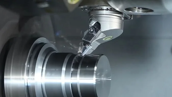
The next step is improving rigidity. The tool should be as short as possible. The boring bar length-to-diameter ratio should be controlled. The turret clamping condition should be checked. The workpiece should be clamped with enough force, but not so much that it deforms. Slender workpieces may need a tailstock, steady rest, or other support. Guideway and slider clearance should also be checked. Lubrication must be clean and stable because poor lubrication increases friction and can create stick-slip vibration.
Structural improvements can help as well. A thicker base, stronger support, and reinforced frame improve low-frequency resistance. Damping pads, rubber, polyurethane, tuned mass blocks, springs, and dampers can reduce vibration transmission. These methods work best after basic rigidity and setup have been corrected. Damping cannot fully correct a loose mechanical system.
Avoid resonance and control the process
Cutting parameters must stay inside a stable zone. Excessive depth of cut, feed rate, and speed increase cutting force. If chatter appears, every value should not be reduced randomly. One factor should be changed at a time. Spindle speed is often adjusted first, because chatter depends strongly on frequency. A small speed change can move the process away from resonance. Feed and depth of cut can then be adjusted based on surface result, tool load, and chip shape.
Tool selection also affects vibration resistance. Sharp inserts reduce cutting force. Stronger edge geometry helps when interrupted cutting is present. Correct nose radius matters. A large nose radius can improve finish in a rigid setup, but it can also increase radial force. In weak setups, a large nose radius may worsen chatter.7 For finishing, stable cutting should be preferred over aggressive productivity.
The working environment matters too. External vibration sources should be reduced. Nearby presses, heavy grinders, forklifts, and unstable floors can disturb precision machining. Temperature and humidity should be controlled when high precision is required. Thermal expansion changes alignment and can move the machine into a less stable condition.
| Improvement area | What should be checked or adjusted | Main purpose |
|---|---|---|
| Rotating system | Dynamic balance of chuck, pulley, rotor, and workpiece | Reduce forced vibration |
| Tool setup | Short overhang and rigid holder | Increase cutting stiffness |
| Workholding | Proper clamping force and added support | Prevent part movement and bending |
| Guideway system | Lubrication, slider clearance, and cleanliness | Reduce friction-related vibration |
| Ballscrew system | Backlash, support bearing condition, and preload | Improve feed stability |
| Spindle system | Bearing noise, heat, runout, and preload | Keep rotation stable |
| Cutting parameters | Speed, feed, and depth of cut | Avoid resonance and reduce cutting force |
| Foundation | Leveling, anchor bolts, and floor rigidity | Prevent low-frequency amplification |
| Damping | Passive dampers or active vibration control | Reduce vibration transmission |
Use maintenance and monitoring as prevention
Prevention is better than emergency correction. Regular spindle runout checks help find bearing problems early. Ballscrew backlash inspection helps prevent feed vibration. Lubrication inspection prevents guideway friction and wear. Leveling checks prevent foundation-related resonance. Vibration monitoring is useful because it can show early warning signs before the surface becomes unacceptable.
Active damping systems can help in high-precision work. Sensors detect vibration in real time. Control elements respond and reduce resonance.8 Passive damping systems are simpler. They use mass blocks, springs, pads, or dampers to absorb energy. Both methods can help, but they work best when the machine is mechanically healthy first.
Conclusion
Vibration on a slant-bed CNC lathe harms finish, accuracy, tool life, and machine health. Stable machining depends on rigidity, balance, maintenance, damping, and suitable cutting parameters.
-
"Mechanical resonance – Wikipedia", https://en.wikipedia.org/wiki/Mechanical_resonance. Resonance occurs in mechanical systems when the frequency of external excitation coincides with a system’s natural frequency, resulting in dramatic amplitude amplification due to constructive interference of oscillations. Evidence role: mechanism; source type: education. Supports: the resonance phenomenon where vibration amplitude increases dramatically when excitation frequency matches natural frequency. ↩
-
"[PDF] Chatter Stability of Machining Operations", https://mtrc.utk.edu/wp-content/uploads/sites/45/2020/08/manu_142_11_110801.pdf. Machining stability research identifies regenerative chatter, a form of self-excited vibration, as particularly problematic because it can grow exponentially from the cutting process itself, often requiring immediate intervention to prevent workpiece damage and tool failure. Evidence role: expert_consensus; source type: research. Supports: the particular severity of self-excited vibration (chatter) in machining operations. ↩
-
"Machining vibrations – Wikipedia", https://en.wikipedia.org/wiki/Machining_vibrations. The regenerative chatter mechanism in machining arises when the cutting tool encounters surface undulations left by previous passes, creating modulated cutting forces that can reinforce and amplify the vibration pattern under certain conditions of cutting speed and system dynamics. Evidence role: mechanism; source type: research. Supports: the regenerative mechanism by which chatter develops through interaction between successive cutting passes. ↩
-
"Slant Bed vs. Flat Bed CNC Lathes: A Comprehensive Comparison …", https://www.blincnc.com/Slant-Bed-vs-Flat-Bed-CNC-Lathes:-A-Comprehensive-Comparison-for-Your-Machine-Shop.html. Machine tool design literature notes that slant-bed configurations facilitate gravity-assisted chip removal and can provide improved structural rigidity through triangulated load paths, though actual performance depends on specific design implementation. Evidence role: general_support; source type: education. Supports: the structural advantages of slant-bed lathe design for chip evacuation and rigidity. Scope note: Comparative advantages vary with specific machine designs and may not apply uniformly across all slant-bed implementations ↩
-
"[PDF] Wear Patterns on Ball Bearings Lubricated by Grease Contaminated …", https://www.tribology.rs/journals/2025/2025-2/2-1893.pdf. Bearing degradation research identifies early-stage wear patterns including surface fatigue on raceways and rolling elements, accompanied by gradual preload reduction and measurable increases in radial runout before catastrophic failure occurs. Evidence role: mechanism; source type: research. Supports: the characteristic progression of bearing wear from initial damage through preload loss to increased runout. ↩
-
"Study on the Influence of Unbalanced Phase Difference … – PMC", https://pmc.ncbi.nlm.nih.gov/articles/PMC11945112/. Rotor dynamics theory establishes that mass imbalance in rotating components generates centrifugal forces that produce vibration at the fundamental rotational frequency and its harmonics, with amplitude proportional to the square of rotational speed. Evidence role: mechanism; source type: education. Supports: how mass imbalance in rotating components generates vibration at frequencies directly related to rotational speed. ↩
-
"A Numerical Model for Predicting the Effect of Tool Nose Radius on …", https://pmc.ncbi.nlm.nih.gov/articles/PMC9104572/. Cutting mechanics research shows that larger nose radii distribute cutting forces over a greater contact length, improving surface finish, but also increase the radial force component, which can reduce stability in systems with limited radial stiffness. Evidence role: mechanism; source type: research. Supports: how tool nose radius affects cutting force direction and machining stability. ↩
-
"Active vibration control for milling operations including frequency …", https://www.sciencedirect.com/science/article/pii/S2212827123001646. Active vibration control systems employ sensors to measure structural vibrations in real time and actuators to apply counteracting forces, achieving vibration reduction through feedback control algorithms, with applications in precision machining and manufacturing. Evidence role: mechanism; source type: research. Supports: the operating principles of active vibration control systems in precision machinery. ↩

Chris Lu
Leveraging over a decade of hands-on experience in the machine tool industry, particularly with CNC machines, I'm here to help. Whether you have questions sparked by this post, need guidance on selecting the right equipment (CNC or conventional), are exploring custom machine solutions, or are ready to discuss a purchase, don't hesitate to CONTACT Me. Let's find the perfect machine tool for your needs.