

What Is the Meaning of “Fake Five-Axis” Achieved by 3+2 Axis CNC Milling Machines?
A five-axis label can create false expectations. Without understanding the actual motion mode, manufacturers may select equipment that cannot machine the required surfaces.
“Fake five-axis” commonly describes 3+2 positioning machining. Two rotary axes set and lock the machining angle, while the X, Y, and Z axes perform the cutting. This method provides five-axis positioning but not continuous five-axis interpolation.
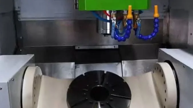
The term “fake five-axis” is informal rather than a recognized technical classification. More accurate terms include 3+2 machining, positional five-axis machining, indexed five-axis machining, and five-axis three-linkage machining1. The number “3” refers to the X, Y, and Z linear axes used together during cutting. The number “2” refers to the two rotary axes used to position the workpiece or spindle.
During a typical operation, the rotary axes move to a programmed angle. The machine then clamps or locks those axes. Milling, drilling, boring, or tapping takes place through three-axis interpolation. Another surface requires the rotary axes to stop cutting, move to a new angle, and lock again.
This method is not defective or useless. It provides an efficient solution for many multi-sided parts. However, it cannot replace simultaneous five-axis machining when the tool direction must change continuously along a surface. Machine buyers should therefore check simultaneous interpolation, RTCP capability, controller functions, and post-processor support instead of relying only on the number of installed axes.
What Types of Parts Are Best Suited for 3+2 “Fake Five-Axis” Machining?
Many complex-looking parts do not require continuous five-axis motion. Selecting a more advanced process than necessary can increase equipment cost and programming time.
3+2 machining is best suited for parts with multiple faces, fixed-angle holes, straight-wall cavities, discrete slopes, and regular pockets. Common examples include gearbox housings, valve blocks, cylinder heads, fixtures, mold inserts, motor housings, and aerospace structural parts.

Which Geometric Features Match 3+2 Machining?
The main selection question concerns tool orientation. A part is suitable when each feature can be machined from one fixed tool direction. The rotary axes place the part at the required angle, and standard three-axis cutting completes the feature. This process works well for planes, pockets, grooves, straight walls, threaded holes, and local inclined surfaces.
Box and housing parts are common applications. Gearbox housings, pump bodies, valve blocks, cylinder heads, and motor housings often contain features on several sides. A three-axis machine may require a separate fixture and setup for every side. A 3+2 machine can expose each side to the spindle without removing the workpiece.
Parts with angled holes also benefit from indexed positioning. The rotary system can align the hole axis with the spindle. A standard drill can then enter perpendicular to the hole opening. This setup can improve hole straightness, positional accuracy, and tool life.
How Does One Clamping Improve Part Accuracy?
Repeated clamping can introduce errors even when each individual operation is accurate. Every setup creates a new relationship between the workpiece, fixture, and machine coordinate system. Small alignment errors can accumulate across several sides2.
A 3+2 process keeps the workpiece in one fixture. The rotary table changes its orientation while the original datum remains available. This arrangement improves the positional relationship between holes, faces, pockets, and reference surfaces. It also reduces loading, unloading, inspection, and fixture preparation time.
Deep cavities and steep walls form another useful application area. Tilting the part can provide a more direct path to the cutting surface. The machine can then use a shorter tool instead of a long tool extending deep into the cavity. A shorter tool bends less and usually permits more stable cutting3.
However, impellers, blisks, turbine blades, propellers, and continuously curved molds4 are generally unsuitable. These parts require the tool direction to change while cutting. Simultaneous five-axis interpolation is normally required to maintain surface contact, avoid interference, and produce a smooth finish.
Does a 3+2 “Fake Five-Axis” CNC Mill Offer Better Rigidity Than a True Five-Axis Machine?
Axis count alone does not determine rigidity. A comparison that ignores the machine body, rotary structure, spindle, fixture, and tool overhang can produce misleading conclusions.
A 3+2 process often provides better dynamic cutting stability because its rotary axes remain locked and shorter tools can be used. However, a 3+2 machine is not automatically more rigid than a true five-axis machine. Structural design and machine quality remain decisive.
Why Can 3+2 Cutting Be More Stable?
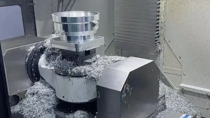
The claimed rigidity advantage mainly concerns the machining mode rather than the machine category. During 3+2 cutting, both rotary axes have already reached their target positions. Their brakes or clamping systems hold them in place. Only the three linear axes participate in interpolation.
This condition usually creates a more stable force path than continuous movement through all five axes. Simultaneous five-axis machining requires the linear and rotary axes to move together. The control system must constantly coordinate their position, speed, acceleration, and direction. Rotary backlash, servo response, thermal change, and changing leverage can influence dynamic performance5.
The comparison becomes clearer when the same five-axis machine performs both modes. That machine may show greater cutting stability in 3+2 mode because its rotary axes remain clamped. However, this result does not prove that a basic modified machine has greater mechanical rigidity than a premium simultaneous five-axis machining center.
| Rigidity factor | 3+2 positioning machining | Simultaneous five-axis machining |
|---|---|---|
| Rotary-axis state | Positioned and locked during cutting | Moving during cutting |
| Number of interpolating axes | Three | Five |
| Dynamic control demand | Relatively lower | Relatively higher |
| Tool overhang | Often shorter | Depends on geometry and collision clearance |
| Heavy material removal | Often highly suitable | Limited by machine and tool posture |
| Complex surface access | Limited | Strong |
| Vibration sensitivity | Often lower at a fixed angle | Depends heavily on structure and servo quality |
Why Does Tool Length Matter?
Tool overhang has a major effect on practical cutting rigidity. A long tool behaves like a lever. Cutting forces create bending, vibration, poor surface quality, and faster tool wear6. Severe deflection can also cause dimensional errors or tool failure.
The tilting function of a 3+2 machine allows the spindle to approach a cavity or inclined surface more directly. This position often permits a shorter end mill, drill, or boring tool. The reduced lever arm improves vibration resistance and supports higher feed rates or deeper cuts.
Machine structure still remains important. A high-quality true five-axis machine may have a stronger bed, larger bearings, better guideways, a more rigid spindle, and more powerful rotary-axis brakes than an inexpensive converted machining center. Such a machine can also run 3+2 programs when heavy cutting is required.
Rigidity should therefore be evaluated through specific machine data. Relevant factors include spindle design, table load, rotary bearing size, clamping torque, guideway structure, tool length, fixture stiffness, and workpiece position. The labels “3+2” and “true five-axis” cannot replace this evaluation.
What Key Limitations Affect a 3+2 Axis CNC Milling Machine?
Five available axes do not guarantee unlimited tool movement. Ignoring the boundary between positioning and simultaneous cutting can cause poor finishes, inefficient programs, or collisions.
The main limitation of 3+2 machining is its fixed tool orientation during cutting. It cannot machine continuously changing free-form surfaces efficiently. Other limits include indexing time, junction marks, rotary positioning errors, restricted collision avoidance, and greater coordinate-management demands.
Why Can It Not Machine Continuously Changing Surfaces?
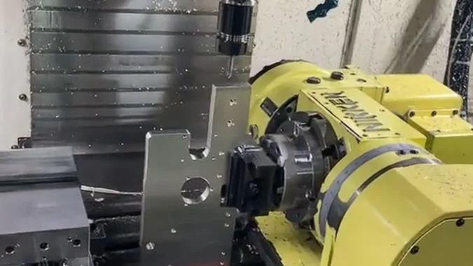
A 3+2 machine changes the rotary-axis position only between cutting operations. After indexing, the tool axis remains fixed relative to the selected working plane. This behavior is suitable for a plane, regular pocket, straight wall, fixed-angle hole, or local slope. It is unsuitable when the required tool vector changes at every point along a surface.
An impeller blade provides a clear example. The tool must follow a twisted surface while avoiding the neighboring blades. The controller must change the tool position and orientation continuously. A fixed-angle operation cannot maintain the required contact and clearance throughout the path.
A free-form surface can sometimes be divided into several indexed sections. However, every section requires a separate orientation and tool path. The boundaries may show steps, blend marks, or uneven surface texture. Additional indexing also adds non-cutting time. This workaround rarely matches the finish and efficiency of simultaneous five-axis machining.
How Do Collision and Positioning Risks Increase?
A simultaneous five-axis machine can change the tool angle during a cut to avoid a fixture, boss, wall, or neighboring feature. A 3+2 process cannot make that adjustment once cutting has begun. An unsuitable fixed angle may force the use of a longer tool. It may also create a collision between the holder, spindle, workpiece, rotary table, or fixture.
Repeated indexing creates another source of error. Every rotary movement depends on axis calibration, encoder accuracy, bearing condition, brake stability, and mechanical repeatability. Small angular errors can become larger linear errors when the cutting point is far from the rotary center7.
RTCP also requires careful explanation. A basic machine marketed as “fake five-axis” may lack Rotation Tool Center Point compensation. In that case, rotary movement changes the physical position of the tool tip relative to the workpiece. Programs, work offsets, and tool lengths must account for that change.
However, 3+2 machining does not always mean that RTCP is absent. A true five-axis machining center can perform indexed 3+2 work while using RTCP or tilted-plane transformation8. The important distinction is whether the machine supports continuous five-axis interpolation and a complete kinematic transformation system.
Can a Standard Three-Axis CNC Machining Center Be Converted into a 3+2 Axis Machine?
Adding a rotary table may appear simple, but hardware alone cannot create a reliable 3+2 system. Poor integration can reduce accuracy, workspace, and operating safety.
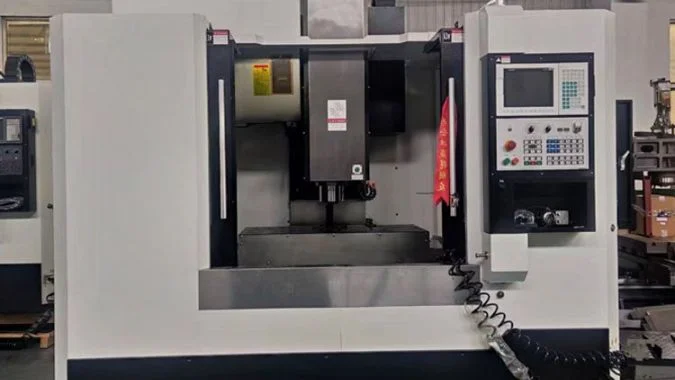
Some three-axis machining centers can be converted by adding a two-axis rotary table or tilting unit. A successful conversion also requires sufficient load capacity, controller support, servo integration, coordinate transformation, CAM programming, a correct post-processor, accurate calibration, and collision protection.
What Hardware Is Required for the Conversion?
A conversion commonly uses a tilt-rotary table, trunnion table, separate rotary and tilting devices, or a swiveling spindle attachment. The selected unit must match the machine’s table dimensions, load capacity, spindle clearance, axis travel, and intended workpiece size.
The added rotary unit occupies part of the original working envelope. Its base raises the workpiece and may reduce the available Z-axis clearance. Tilting also increases the space needed around the part. A workpiece that fits comfortably on the original table may collide with the spindle, enclosure, or machine column after conversion.
The table must support the extra mass of the rotary unit, fixture, and workpiece. The foundation and guideways must also withstand the changed load distribution. Rotary brakes require enough holding torque to resist milling forces. A lightly built indexing table may perform drilling but move or vibrate during heavy side milling.
Why Are Control and Software Functions Essential?
The CNC controller must recognize and control the two added rotary axes. Some systems require new axis cards, servo drives, software options, PLC changes, and parameter settings. Older controllers may support only a simple indexer rather than fully programmable rotary positioning.
Useful control functions include coordinate rotation, tilted working planes, tool-length compensation, and machine kinematic transformation. Examples include G68 functions and controller-specific cycles such as CYCLE8009. Available functions depend on the controller model and licensed software options.
CAM software must support 3+2 tool-path creation. A machine-specific post-processor must convert tool-axis vectors into valid rotary positions and XYZ coordinates. The post-processor must understand the rotary-axis direction, travel limits, pivot points, preferred angular solution, and machine structure. Incorrect output can command an unexpected rotation or serious collision.
Calibration completes the conversion. The rotary centers, axis alignment, backlash, work offsets, and indexing repeatability must be measured and corrected10. Test parts should verify hole position and surface relationships at several angles. Warranty conditions, electrical rules, guarding, and local safety requirements also need review. When the original machine lacks sufficient rigidity, controller capacity, or workspace, a purpose-built 3+2 or true five-axis machine is usually the safer choice.
Conclusion
3+2 machining provides stable and economical multi-angle production, while simultaneous five-axis machining remains necessary for continuous surfaces, changing tool orientations, and advanced collision avoidance11.
-
"Feasibility of 8-Shaped Motion Test for Five-Axis Machining Center", https://www.fujipress.jp/ijat/au/ijate001700050477/. Industry standards and technical literature use terms such as indexed five-axis, 3+2 positioning, and positional five-axis to describe machining where rotary axes lock during cutting operations, distinguishing this mode from simultaneous five-axis interpolation. Evidence role: definition; source type: research. Supports: the technical terminology used in CNC machining to distinguish positioning from simultaneous five-axis operations. Scope note: Terminology may vary across different manufacturing regions and standards organizations. ↩
-
"Uncertainties for Machine Tool Modeling", https://nvlpubs.nist.gov/nistpubs/ams/NIST.AMS.100-36.pdf. Metrology studies demonstrate that each workpiece setup introduces independent alignment errors that can compound when features on different faces must maintain tight positional relationships, with typical setup repeatability ranging from 0.005 to 0.025 mm depending on fixturing method. Evidence role: mechanism; source type: research. Supports: the propagation of positioning errors through multiple setup operations in precision machining. ↩
-
"Comparison of wood composite properties using cantilever …", https://bioresources.cnr.ncsu.edu/resources/comparison-of-wood-composite-properties-using-cantilever-beam-bending/. Machining dynamics research shows that tool deflection increases with the cube of overhang length for a cantilever beam, making length-to-diameter ratio a critical parameter for cutting stability, with ratios below 3:1 generally providing significantly better vibration resistance than ratios above 5:1. Evidence role: mechanism; source type: research. Supports: the mechanical relationship between tool extension length and cutting stability. ↩
-
"Improvement in the efficiency of the five-axis machining of aerospace …", https://pmc.ncbi.nlm.nih.gov/articles/PMC10450602/. Aerospace manufacturing literature documents that components with continuously varying surface normals, such as turbine blades and impellers, require simultaneous five-axis interpolation to maintain optimal tool contact angle and avoid gouging on adjacent surfaces. Evidence role: case_reference; source type: research. Supports: the machining requirements for complex curved aerospace and turbomachinery components. Scope note: Some simpler blade geometries may be machinable with advanced 3+2 strategies using multiple indexed positions. ↩
-
"Zero Backlash CNC Rotary Tables for 5-Axis Machining – UCAM", https://ucamind.com/zero-backlash-cnc-rotary-tables-5-axis-machining/. Machine tool research identifies rotary axis backlash, servo bandwidth limitations, thermal expansion of rotary components, and position-dependent mechanical advantage as significant contributors to contouring errors in simultaneous five-axis operations, with combined effects potentially reaching 0.05-0.15 mm under typical production conditions. Evidence role: mechanism; source type: research. Supports: the factors affecting positioning accuracy and dynamic performance in multi-axis machining systems. ↩
-
"Effect of Machining Feed on Surface Roughness in Cutting 6061 Aluminum", https://open.clemson.edu/cgi/viewcontent.cgi?article=1060&context=auto_eng_pub. Machining research demonstrates that cutting tool deflection follows cantilever beam mechanics, with lateral displacement proportional to the cube of overhang length, and natural frequency inversely proportional to length squared, resulting in measurably degraded surface finish and increased tool wear when length-to-diameter ratios exceed recommended limits. Evidence role: mechanism; source type: research. Supports: the mechanical effects of tool extension on cutting performance. ↩
-
"A Method for Simultaneously Measuring 6DOF Geometric Motion …", https://pmc.ncbi.nlm.nih.gov/articles/PMC6514671/. Geometric analysis shows that angular positioning error in a rotary axis produces linear displacement at the tool tip equal to the radius multiplied by the angle in radians, meaning a 0.001° angular error creates approximately 0.017 mm linear error at a 1000 mm radius. Evidence role: mechanism; source type: research. Supports: the geometric amplification of rotary axis positioning errors. ↩
-
"Simultaneous 5-Axis Machining with RTCP", https://www.optipro.com/blog/rtcp/. CNC control system documentation defines Rotation Tool Center Point (RTCP) as a kinematic transformation that automatically adjusts linear axis positions to maintain the programmed tool tip location when rotary axes move, compensating for the geometric offset between the rotation center and cutting point. Evidence role: definition; source type: education. Supports: the coordinate transformation methods used to maintain tool center point position during rotary axis movement. Scope note: Implementation details and terminology vary among controller manufacturers (also called TCPM, TRAORI, or similar proprietary names). ↩
-
"G68 & G69 G Codes: CNC Coordinate Rotation [ Easy Tutorial & Guide ]", https://www.cnccookbook.com/g68-g69-rotate-coordinate-cnc-g-code/. CNC programming standards and controller manuals document G68 as a coordinate rotation function in ISO/EIA programming, while CYCLE800 represents a manufacturer-specific (Siemens) implementation for tilted working plane transformation in multi-axis applications. Evidence role: definition; source type: education. Supports: the programming functions used for coordinate system manipulation in CNC machining. Scope note: Function availability and syntax vary significantly among different CNC controller brands and models. ↩
-
"Variability in the Geometric Accuracy of Additively …", http://utw10945.utweb.utexas.edu/Manuscripts/2010/2010-01-Cooke.pdf. International standards for machine tool testing (ISO 230 series and ISO 10791-6) specify measurement procedures for rotary axis location, alignment, backlash, and positioning repeatability as essential parameters for verifying five-axis machine geometric accuracy. Evidence role: general_support; source type: institution. Supports: the calibration parameters critical to five-axis machine accuracy. ↩
-
"3+2 vs. Simultaneous 5-Axis Machining: Which Approach Fits …", https://www.methodsmachine.com/blog/32-vs-simultaneous-5-axis-machining-which-approach-fits-your-shop/. Manufacturing research demonstrates that surfaces with continuously varying curvature, applications requiring dynamic tool orientation adjustment, and real-time collision avoidance in constrained geometries necessitate simultaneous five-axis interpolation to maintain surface quality and prevent interference. Evidence role: general_support; source type: research. Supports: the machining scenarios that require continuous five-axis interpolation. Scope note: Some applications may be achievable through advanced 3+2 strategies with very fine angular indexing, though typically with longer cycle times. ↩

Chris Lu
Leveraging over a decade of hands-on experience in the machine tool industry, particularly with CNC machines, I'm here to help. Whether you have questions sparked by this post, need guidance on selecting the right equipment (CNC or conventional), are exploring custom machine solutions, or are ready to discuss a purchase, don't hesitate to CONTACT Me. Let's find the perfect machine tool for your needs.