

What Kind of Guide Rail Is More Suitable for Heavy-Duty Lathe?
Machining massive steel forgings demands absolute structural stability. When evaluating a heavy-duty lathe, selecting the correct guide rail system is a critical engineering decision to ensure machine rigidity and prevent tool-destroying vibrations during deep cuts.
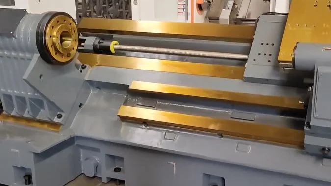
Box ways, also called hard rails, fit heavy-duty lathes best. They use sliding friction with a large surface contact area. This solid iron structure provides massive load capacity and excellent vibration damping. They easily cut large, heavy, and hard metal parts.
Choosing between linear guides and box ways is rarely a simple choice; it requires matching the machine’s mechanical limits to your specific machining operations. Below is a detailed technical comparison of these two guide rail systems to help your team specify the exact configuration needed for your heavy metal applications.
What Are the Primary Differences Between Linear Rails and Hard Rails for Lathes?
Specifying the right CNC lathe requires balancing rapid traverse speeds with load-bearing capacity. Understanding the fundamental engineering differences between linear and hard rails is essential for your procurement and engineering teams to match the machine’s architecture to your production requirements.
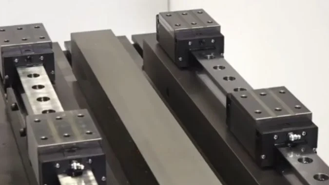
Linear rails use rolling metal balls to provide fast motion for light parts. Hard rails use flat iron sliding on iron to provide massive strength. Hard rails handle extreme weight. Linear rails focus on high speed and high precision.
A hard rail is a box way. The factory casts it directly into the iron machine bed. Workers scrape the iron by hand.1 They make it perfectly flat. We often add a plastic coating. This coating helps the metal slide. This system uses sliding friction. The flat surfaces touch each other completely.
A linear rail uses a totally different design. It uses a modular steel track. A metal carriage rides on this track. Small steel balls spin inside the carriage.2 This creates rolling friction. The small balls only touch the track at tiny points.3
These physical differences change machine performance. Hard rails take heavy loads. They move slowly. Linear rails move very fast. They cannot take heavy shocks.4 Hard rails need careful oil maintenance. They need manual scraping to fix. Linear rails cost more money at first. You can unbolt and replace them easily.
| Feature | Hard Rails (Box Ways) | Linear Rails (Linear Guides) |
|---|---|---|
| Friction Type | Sliding friction | Rolling friction |
| Contact Area | Large flat surface | Tiny point or line |
| Operating Speed | Low speed | Very high speed |
| Maintenance | Hard to fix, needs scraping | Easy to unbolt and replace |
Why Are Hard Rail Traditionally Considered the Standard for Heavy-Duty Turning?
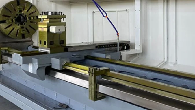
Supporting multi-ton workpieces, such as massive steel shafts, requires a machine bed engineered for extreme loads. Hard rails are strictly specified for these heavy-duty applications because their design safely distributes massive weight across a large surface area, resisting structural deflection.
Hard rails act as the standard for heavy turning because they use massive surface contact. The flat iron sections disperse heavy weight over a huge area. This stops the machine from bending under extreme loads and heavy cutting forces.
Good hard rails last for decades. They survive terrible conditions. We consider them the absolute standard for rough machining. They possess raw physical strength. Linear rails use tiny steel balls. A heavy three-ton part will crush those tiny balls.
Hard rails use solid flat iron. The contact area is huge. This huge area spreads the heavy load. You push a heavy cutting tool deep into a forged steel blank. The flat iron rails do not bend. They support the cutting tool perfectly. We harden the iron rail surface. This makes the rail resist wear. It moves heavy loads every day without breaking.
Hard rails also survive dirty workshops. Heavy turning makes hot metal chips. It makes thick iron dust. Linear rails break easily. Dirt gets into the tiny balls. Hard rails push the dirt away. The simple sliding block ignores the bad environment. You cut giant steel castings all day long. The machine stays strong.
| Standard Feature | Hard Rail Advantage | Result on Factory Floor |
|---|---|---|
| Weight Support | Huge surface contact | Safely holds three-ton parts |
| Wear Resistance | Hardened iron surface | Lasts years under heavy load |
| Dirty Conditions | No small rolling parts | Survives dust and hot chips |
| Structural Bend | Cast as one heavy piece | Stays straight during deep cuts |
How Do Hard Rails Improve Vibration Damping During Large-Diameter Interrupted Cutting?
Interrupted cutting on large-diameter parts, such as gear blanks, inevitably introduces severe shock loads to the spindle and tool. Hard rails are widely adopted here because their massive sliding contact area provides the necessary vibration damping to maintain surface finish and protect tooling investments.
Hard rails absorb vibration through sliding friction. The large metal-to-metal contact acts like a giant sponge for shock waves. This massive iron structure stops the tool from shaking when it hits gaps in large-diameter parts.
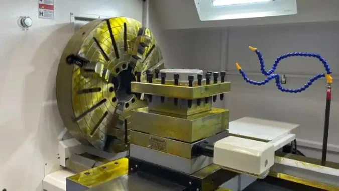
Large pump bodies have holes and gaps. The cutting tool hits the metal. Then it hits empty air. Then it hits the metal again. We call this interrupted cutting. It creates terrible shock waves.5
A linear rail bounces. The tiny balls cannot absorb the heavy impact. The machine shakes violently. A hard rail eats the vibration completely. The solid iron bed and the flat sliding carriage press together. Thick oil sits between the flat plates. This oil acts like a heavy cushion. It kills the vibration instantly. Your spindle stays still.
You must use good machining tricks too. You use a steady rest to hold long parts. You lower your cutting speed. You take smaller cuts. This avoids machine resonance. You also change your tool shape. A larger lead angle pushes the force down.6 It pushes into the heavy iron bed. The hard rails take that force. They keep the cut perfectly smooth.
| Damping Method | How It Works | Benefit for Machining |
|---|---|---|
| Sliding Friction | Heavy flat plates rub together | Absorbs sudden crash shocks |
| Oil Cushion | Thick oil sits between plates | Kills high-frequency chatter |
| Machine Setup | Steady rests hold the part | Stops long parts from bending |
| Tool Geometry | Large lead angle | Pushes force into the iron bed |
What Kinds of Workpieces Are Suitable for Heavy-Duty Turning?
Expanding your facility’s capabilities to handle heavy-duty turning requires a clear understanding of your target applications. Identifying the specific workpiece dimensions, weights, and tough materials that necessitate a heavy-duty lathe is a crucial step in justifying the capital investment.
Heavy-duty turning suits massive shafts, large gear blanks, and heavy forged cylinders. These parts usually weigh over five hundred kilograms. They use tough alloy steel. They require you to remove huge amounts of rough metal quickly.
You put massive rotating bodies on these machines. We see giant ship crankshafts. We see wind turbine spindles. We machine huge oil pipes. These parts have diameters over five hundred millimeters. A single piece weighs thousands of kilograms. You cut very tough metal. Customers cut high-strength alloy steel. They cut duplex stainless steel.
These big parts start as rough castings. They start as raw forgings. They have thick scale on the outside. You must cut away large amounts of metal. You cut it very fast. You take deep cuts. You feed the tool quickly. You cannot do this on a light machine. You also use heavy machines for thin-walled rings. The heavy iron bed stops the ring from vibrating. You sell these parts to energy plants.
| Workpiece Type | Examples | Why It Needs Heavy Turning |
|---|---|---|
| Massive Shafts | Ship cranks, turbine spindles | Weighs thousands of kilograms |
| Large Discs | Hubs, big gear blanks | Very wide diameter |
| Tough Metals | Duplex steel, hard alloys | Needs massive cutting force |
| Rough Blanks | Raw forgings, iron castings | Needs fast metal removal |
Conclusion
Hard rails provide the immense strength and vibration damping needed for heavy-duty lathes. Choose linear rails for speed. Rely on hard rails for massive metal parts.
-
"Hand scraper – Wikipedia", https://en.wikipedia.org/wiki/Hand_scraper. Sources on machine-tool scraping describe hand scraping as a traditional finishing process used to correct geometry, improve bearing contact, and prepare precision sliding surfaces. Evidence role: mechanism; source type: education. Supports: Hand scraping is used to finish or correct machine-tool sliding guide surfaces.. Scope note: The source would support hand scraping as a known process, not that every factory or every hard-rail lathe uses manual scraping today. ↩
-
"[PDF] Topic 16 Rolling element linear motion bearings – MIT", https://web.mit.edu/2.70/Lecture%20Materials/Documents/Week%2004/PMD%20Topic%2016%20Rolling%20linear.pdf. References on linear motion guideways describe recirculating-ball linear guides as carriages or blocks containing rolling steel balls that circulate between the block and rail. Evidence role: definition; source type: institution. Supports: Many linear rails use steel balls inside a carriage to create rolling motion.. Scope note: This supports ball-type linear guides specifically; some linear guide systems use rollers, hydrostatic bearings, or other arrangements. ↩
-
"[PDF] Tutorial on Hertz Contact Stress", https://wp.optics.arizona.edu/optomech/wp-content/uploads/sites/53/2016/10/OPTI-521-Tutorial-on-Hertz-contact-stress-Xiaoyin-Zhu.pdf. Mechanical engineering references on rolling-element contacts explain that balls transmit load through small Hertzian contact patches rather than broad surface contact. Evidence role: mechanism; source type: education. Supports: Ball-type linear guides concentrate contact into very small contact regions compared with box ways.. Scope note: In practice the contact is a small elliptical area under load, not a mathematical point, and dimensions depend on preload, geometry, and material. ↩
-
"Topic 16 Rolling element linear motion bearings", https://web.mit.edu/2.70/Lecture%20Materials/Documents/Week%2004/PMD%20Topic%2016%20Rolling%20linear.pdf. Linear-guideway references describe rolling-element guides as low-friction systems suitable for high-speed motion, while manufacturer-neutral engineering texts note that rolling contacts can be more sensitive to shock loading than broad sliding guideways. Evidence role: expert_consensus; source type: education. Supports: Linear rails are associated with high-speed motion but are generally less tolerant of severe shock than heavy sliding ways.. Scope note: The claim is comparative and depends on guide size, preload, roller versus ball design, and load rating; properly specified linear guides can withstand significant loads. ↩
-
"[PDF] MODULATED TOOL PATH TURNING STABILITY ANALYSIS", https://mtrc.utk.edu/wp-content/uploads/sites/45/2019/09/5079.pdf. Research on interrupted cutting and milling/turning dynamics reports that intermittent tool engagement produces impact-like force fluctuations and vibration excitation in the tool-workpiece-machine system. Evidence role: mechanism; source type: paper. Supports: Interrupted cutting creates severe transient loads and vibration excitation.. Scope note: The phrase “terrible shock waves” is informal; a source would more precisely support transient cutting-force impacts and vibration, not necessarily literal shock waves in all cases. ↩
-
"[PDF] Cutting Forces in Turning Operations – UPCommons", https://upcommons.upc.edu/server/api/core/bitstreams/41a080fb-49e9-4f68-9a6c-5e2d04eb950f/content. Metal-cutting mechanics references explain that tool approach or lead angle changes the direction and components of cutting force, redistributing load among tangential, feed, and radial directions. Evidence role: mechanism; source type: education. Supports: Changing lead angle alters the direction of cutting-force components during turning.. Scope note: The exact direction and magnitude of force components depend on the convention used for lead/approach angle, tool geometry, material, and cutting parameters. ↩

Chris Lu
Leveraging over a decade of hands-on experience in the machine tool industry, particularly with CNC machines, I'm here to help. Whether you have questions sparked by this post, need guidance on selecting the right equipment (CNC or conventional), are exploring custom machine solutions, or are ready to discuss a purchase, don't hesitate to CONTACT Me. Let's find the perfect machine tool for your needs.