

Why Does a Boiler Drum Shake During CNC Drilling?
A shaking boiler drum can spoil hole accuracy and damage tooling. Troubleshooting should locate the movement and check both workholding stability and drill entry conditions.
A boiler drum can shake when drilling forces act on loose clamping, poorly positioned supports, or a flexible setup. Tool runout, uneven entry engagement, and chip problems can also create vibration. Diagnosis requires separate measurements of drum movement, support movement, and tool behavior under comparable cutting conditions.
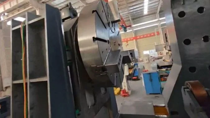
In the reported inspection, the engineer suspected unstable support of the drum’s weight, inconsistent chuck grip, and an off-center U-drill. A crown drill was proposed for another trial. That recommendation remained unverified because the replacement tool was unavailable. The support arrangement therefore needed its own inspection before the next cutting test could produce useful evidence.
How Should V-Support Height and Position Be Checked Before Drilling?
A raised support may still carry little load or disturb drum alignment. The inspection must confirm loaded contact, mounting security, and position against the established datum.
V-supports should be checked under the drum’s actual load against the machine’s setup datum and clamping axis. Each support must contact the intended area, hold its adjusted position, and remain secure at its base. Height and spacing should suit the drum geometry and drilling location.
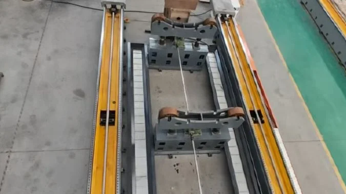
Check the complete support assembly
The proposed retrofit retained two support assemblies. The plan included removing the original bottom shims, fitting steel plates for adjustable positioning, and adding motor-driven lifting to both supports. Support mounting holes, motor brackets, and mounting datums were to be prepared before the engineer arrived.
These were proposed changes. Their completion and loaded performance still required verification.
An inspection should follow the load from the drum contact surfaces through the lifting mechanism and connections to the machine base.
| Inspection point | What needs checking | Why it matters |
|---|---|---|
| Mounting surfaces | Clean seating, correct datums, and secure plate connections | A moving base defeats the support above it |
| Loaded support height | Drum alignment before and after adjustment | Excessive lift can disturb the chuck alignment |
| Support spacing | Contact positions relative to drum weight and the drilling area | Poor spacing can leave a weakly supported span |
| Lifting and holding mechanism | Stable height after adjustment and secure locking as designed | Motor movement alone does not prove load holding |
| Drum and chuck contact | Actual diameter, shape variation, and jaw engagement | Diameter variation can change the grip and load distribution |
Measure alignment in the loaded condition
Nominally equal support heights do not automatically establish the correct drum centerline. Diameter variation, ovality, and unequal contact can change the loaded position.1 The inspection should use the agreed machine and workpiece references.
A support set too low may leave a gap. A support set too high may lift or distort the drum against the chuck. Both conditions can affect drilling stability.
The final readings should be recorded after clamping and locking. Limits for alignment, contact, and movement should follow the equipment design and acceptance plan. The drum coordinate system should then be checked against that verified setup.
How Can a Trial Cut Separate Workholding Movement from Tool Vibration?
Visible shaking does not identify the moving interface. A controlled trial should track the drum, support structure, and tool through each stage of drilling.
A trial cut can separate the causes by measuring drum movement relative to the fixture and support movement relative to the machine base, alongside tool behavior. The comparison should cover approach, entry, full engagement, and breakthrough. Each trial should change one condition and retain the same measurement references.
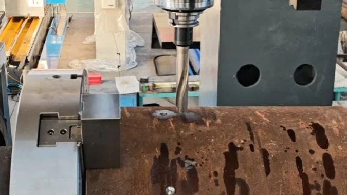
Establish a traceable baseline
The trial should begin with confirmed secure clamping. Its record should identify the drum, hole location, support positions, clamp settings, drill, holder, overhang, speed, feed, and coolant condition.
The measurement arrangement should distinguish movement across separate interfaces. An indicator attached to a support that moves with the drum may miss movement of the entire assembly.2 Suitable instruments need stable reference points outside the suspected moving joint.
Stopped measurements before and after cutting can reveal a permanent shift. Dynamic displacement or vibration measurements are needed to capture movement that disappears after the cutting load is removed.
| Trial stage | Observation to record | What the evidence can suggest |
|---|---|---|
| Spindle running before contact | Vibration at the spindle or holder | A rotating assembly problem may exist independently of cutting |
| Initial entry | Drum displacement, support movement, and tool deflection | Uneven engagement may expose a weak setup or unstable tool |
| Full engagement | Continued movement, load variation, and chip flow | Support flexibility, tool vibration, or chip congestion needs checking |
| Breakthrough and withdrawal | Sudden movement and any remaining datum shift | The changing load may reveal slip or elastic movement |
Compare equivalent cutting conditions
A support comparison should retain the same tooling and cutting settings wherever practical. Equivalent unmachined hole positions should have comparable wall thickness, entry shape, and support distance.
Sound, video, spindle load, and hole quality provide supporting evidence. None identifies the root cause alone.
Relative slip at the chuck points toward a holding problem. Movement that returns to zero can indicate elastic deflection.3 A stable reading at one location does not exclude local shell vibration elsewhere. The inspection needs enough measurement points to distinguish these responses.
Why Should Drill Type and Entry Conditions Be Checked Alongside Workholding?
A secure drum can still experience unstable drilling forces. The drill design, mounting, and entry geometry must be checked before a tool change is judged effective.
Drill type and entry conditions determine the forces applied to the workholding. A curved or uneven surface can load cutting edges unevenly during entry. Drill alignment, overhang, edge condition, feed, and coolant must match the application. A replacement drill needs a documented trial before its benefit can be confirmed.
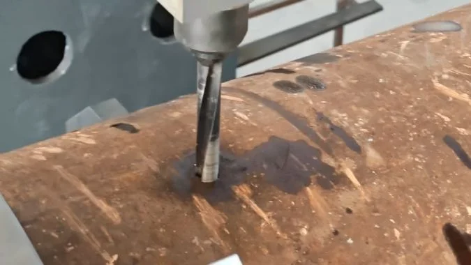
Define the suspected tooling fault
The engineer suspected an off-center U-drill. That description needs a measurable definition. Tool-axis runout, misalignment with the intended hole, and sideways deflection during entry are different conditions.
An indexable drill can have different central and peripheral inserts by design.4 Their appearance alone cannot establish incorrect centering. Runout and alignment should be checked at the points specified for the actual drill and holder.
The proposed crown drill also needs a manufacturer and model identification. The name alone does not establish its cutting geometry or suitability for the drum surface.
| Tooling item | Information needed before the trial | Purpose |
|---|---|---|
| Drill model and structure | Cutting diameter, tip or insert design, and application limits | Establishes the correct entry procedure |
| Tool mounting | Holder condition, seating, alignment, and measured runout | Separates mounting faults from cutting deflection |
| Tool length | Required reach and actual overhang | Identifies avoidable flexibility |
| Entry surface | Curvature, local slope, and surface irregularities | Shows how the cutting edges first engage |
| Cutting conditions | Entry feed, full-cut feed, speed, and coolant delivery | Makes the trial reproducible |
Match the entry method to the actual tool
Curved and irregular surfaces can create uneven engagement before the drill reaches full diameter.5 Different drill designs require different entry strategies.
Any feed reduction, pilot operation, or local surface preparation should follow the selected drill’s instructions and the part drawing. A recommendation for one drill design should not automatically be transferred to another.
The replacement drill may require different settings. Those changes must be recorded because the comparison then evaluates the combined tool and process change. In the reported inspection, the replacement trial remained open, so improved stability could not yet be claimed.
What Evidence Is Needed to Confirm That a Workholding Retrofit Has Solved the Problem?
Completed installation and a running machine leave the original fault unproven. Acceptance needs recorded movement checks and repeatable hole quality under agreed production conditions.
A workholding retrofit is verified by documented modifications, measured control of drum and support movement, and conforming holes across repeated trials. The records must identify comparable cutting conditions and agreed acceptance limits. Installation completion, machine operation, and resolution of the original shaking problem each require separate evidence.
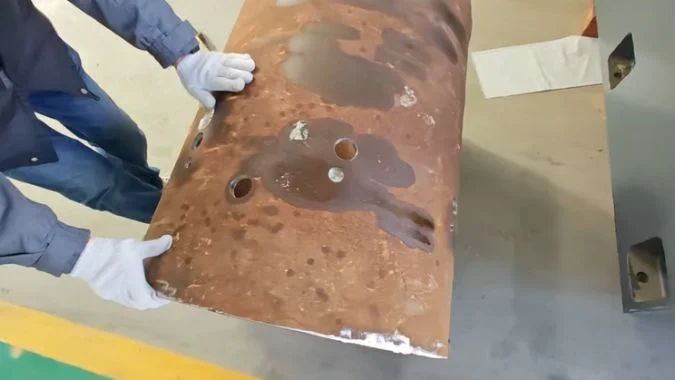
Connect each modification to a measured result
The available records covered installation, commissioning, trial operation, training, and proposed support and hydraulic changes. Re-acceptance with a suitable drill remained outstanding, and final sign-off was incomplete.
A verification report should identify which changes were completed and how they compare with the approved plan. Photographs and installation checks establish the physical arrangement. Loaded measurements and cutting results establish its performance.
| Evidence required | What the record should contain | What it establishes |
|---|---|---|
| Completed modifications | Support locations, plates, connections, lifting arrangements, and applicable hydraulic changes | The installed configuration matches the agreed work |
| Comparable trial conditions | Drum details, hole locations, tooling, clamps, supports, and cutting settings | Results can be compared meaningfully |
| Movement measurements | Drum-to-fixture and support-to-base readings during and after cutting | The setup maintains position within agreed limits |
| Hole inspection | Drawing-based size, position, orientation, and surface checks | The process produces acceptable features |
| Repeated trials | Results across representative positions and repeated cycles | The improvement is consistent within the tested conditions |
| Acceptance decision | Recorded limits, results, remaining issues, and sign-off | The conclusion has a defined basis |
Verify the claimed operating range
A successful hole close to a support may not represent a hole farther along the drum. Trials should include positions that previously showed shaking and other demanding locations within the agreed operating range.
The same principle applies to drum diameters. An adjustable support arrangement needs verification for the sizes covered by the acceptance claim.
If workholding and tooling change together, successful results support acceptance of the combined configuration. They do not isolate the contribution of either change. Without a comparable earlier baseline, the report can establish current performance but cannot quantify the improvement.
The conclusion should state the tested conditions, measured results, and remaining limits. In this case, the supplied records support a troubleshooting and re-inspection plan. They do not yet establish that the original shaking was eliminated.
Conclusion
Boiler drum shaking needs separate checks of workholding movement and cutting vibration. A retrofit is proven through measured stability and repeatable hole quality under documented conditions.
-
"Dynamic Screw Lead Accuracy Measurement – PMC", https://pmc.ncbi.nlm.nih.gov/articles/PMC11548596/. Geometric dimensioning and tolerancing principles show that out-of-roundness and diameter variation alter contact points between cylindrical workpieces and V-supports, shifting the effective center position and potentially creating unstable support conditions. Evidence role: mechanism; source type: education. Supports: How cylindrical form deviations influence support contact and positioning. ↩
-
"Development of a metrology frame to improve the positioning accuracy …", https://www.nist.gov/publications/development-metrology-frame-improve-positioning-accuracy-micromeso-scale-machine-tools. Metrology standards establish that displacement measurements require a reference frame independent of the moving system; sensors mounted to components that move with the measured object cannot detect motion of the entire assembly relative to external references. Evidence role: general_support; source type: education. Supports: The requirement for measurement references to be independent of the measured system. ↩
-
"Effect of machining fixture design parameters on workpiece …", https://pure.psu.edu/en/publications/effect-of-machining-fixture-design-parameters-on-workpiece-displa. Mechanical engineering analysis distinguishes between permanent displacement indicating interface slip or plastic deformation, and recoverable displacement indicating elastic deflection; this distinction is fundamental to diagnosing whether workholding failures involve inadequate clamping force or insufficient structural rigidity. Evidence role: mechanism; source type: education. Supports: How displacement characteristics distinguish between clamping slip and elastic deflection. ↩
-
"Indexable Insert type Drill SumiDrill GDX series | SUMITOMO …", https://www.sumitool.com/en/products/cutting-tools/drills/gdx.html. Modern indexable drill designs commonly employ different insert geometries for central and peripheral positions to optimize cutting conditions across the drill diameter, with center inserts handling lower cutting speeds and peripheral inserts managing higher speeds and chip evacuation. Evidence role: general_support; source type: education. Supports: The use of different insert types in indexable drill designs. ↩
-
"Drill-Point Geometry, Thrust Force, Feed Work, and Hole Diameter – PMC", https://pmc.ncbi.nlm.nih.gov/articles/PMC13665967/. Drilling process mechanics establish that surface curvature and irregularities cause cutting edges to engage progressively rather than simultaneously, with the resulting time-varying forces potentially causing tool deflection and vibration until the drill achieves stable full-diameter engagement. Evidence role: mechanism; source type: education. Supports: How surface irregularities affect the sequence of cutting edge engagement. ↩

Chris Lu
Leveraging over a decade of hands-on experience in the machine tool industry, particularly with CNC machines, I'm here to help. Whether you have questions sparked by this post, need guidance on selecting the right equipment (CNC or conventional), are exploring custom machine solutions, or are ready to discuss a purchase, don't hesitate to CONTACT Me. Let's find the perfect machine tool for your needs.