

Waarom trilt een keteltrommel tijdens het CNC-boren?
Een trillende keteltrommel kan de nauwkeurigheid van het gat bederven en gereedschap beschadigen. Bij probleemoplossing moet de beweging worden gelokaliseerd en moeten zowel de stabiliteit van de opspanning als de condities bij het boren worden gecontroleerd.
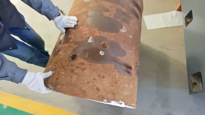
Een keteltrommel kan trillen wanneer boorkrachten inwerken op een losse klemming, slecht geplaatste steunen of een flexibele opstelling. Ook uitloop van het gereedschap, ongelijkmatige aanzet en spaanproblemen kunnen trillingen veroorzaken. Diagnose vereist afzonderlijke metingen van de trommelbeweging, de steunbeweging en het gereedschapsgedrag onder vergelijkbare snijomstandigheden.
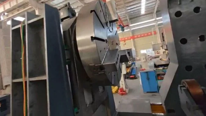
Tijdens de gerapporteerde inspectie vermoedde de ingenieur een instabiele ondersteuning van het trommelgewicht, inconsistente grip van de klauwplaat en een excentrische U-boor. Voor een volgende test werd een kroonboor voorgesteld. Die aanbeveling bleef onverifieerd omdat het vervangende gereedschap niet beschikbaar was. De steunconstructie vereiste daarom een eigen inspectie voordat de volgende snijtest nuttige bewijzen kon opleveren.
Hoe moeten de hoogte en positie van de V-steun worden gecontroleerd vóór het boren?
Een verhoogde steun kan mogelijk weinig belasting dragen of de uitlijning van de trommel verstoren. De inspectie moet het belast contact, de veiligheid van de montage en de positie ten opzichte van het vastgestelde referentievlak bevestigen.
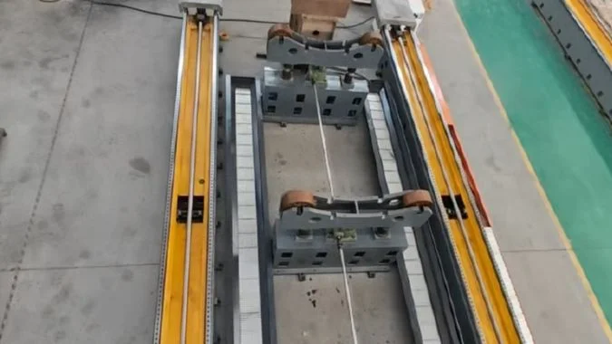
V-steunen moeten onder de werkelijke belasting van de trommel worden gecontroleerd ten opzichte van het referentievlak en de klem-as van de machine. Elke steun moet het beoogde gebied raken, de ingestelde positie behouden en stevig op zijn basis blijven staan. Hoogte en tussenruimte moeten passen bij de geometrie van de trommel en de boorlocatie.
Controleer de volledige steunassemblage
De voorgestelde aanpassing behield twee steunassemblages. Het plan omvatte het verwijderen van de originele onderlegplaatjes, het plaatsen van stalen platen voor verstelbare positionering en het toevoegen van een motoraangedreven hefmechanisme aan beide steunen. Bevestigingsgaten voor de steunen, motorbeugels en montagereferenties moesten worden voorbereid voordat de ingenieur arriveerde.
Dit waren voorgestelde wijzigingen. De voltooiing en de prestaties onder belasting moesten nog worden geverifieerd.
Een inspectie moet de belasting volgen vanaf de contactoppervlakken van de trommel via het hefmechanisme en de verbindingen naar de machinebasis.
| Inspectiepunt | Wat moet worden gecontroleerd | Waarom dit belangrijk is |
|---|---|---|
| Montageoppervlakken | Schone zitting, correcte referentievlakken en veilige plaatverbindingen | Een bewegende basis maakt de steun erboven ondoeltreffend |
| Hoogte van de belaste steun | Uitlijning van de trommel voor en na afstelling | Overmatig heffen kan de uitlijning van de klauwplaat verstoren |
| Tussenruimte van de steunen | Contactposities ten opzichte van het trommelgewicht en het boorgebied | Slechte tussenruimte kan een zwak ondersteunde overspanning achterlaten |
| Hef- en houdmechanisme | Stabiele hoogte na afstelling en veilige vergrendeling zoals ontworpen | Beweging van de motor alleen bewijst niet dat de last behouden blijft |
| Contact tussen trommel en klauwplaat | Werkelijke diameter, variatie in vorm en aangrijping van de bek | Diametervariatie kan de grip en de lastverdeling veranderen |
Meet de uitlijning in belaste toestand
Nominaal gelijke steunhoogtes bepalen niet automatisch de juiste hartlijn van de trommel. Diametervariatie, ovaliteit en ongelijkmatig contact kunnen de belaste positie veranderen.1 De inspectie moet gebruikmaken van de overeengekomen machine- en werkstukreferenties.
Een steun die te laag is ingesteld, kan een opening achterlaten. Een steun die te hoog is ingesteld, kan de trommel tegen de klauwplaat opheffen of vervormen. Beide omstandigheden kunnen de boorstabiliteit beïnvloeden.
De definitieve waarden moeten worden vastgelegd na het klemmen en vergrendelen. Limieten voor uitlijning, contact en beweging moeten het ontwerp van de apparatuur en het acceptatieplan volgen. Het coördinatensysteem van de trommel moet vervolgens worden gecontroleerd aan de hand van die geverifieerde opstelling.
Hoe kan een proefsnede beweging van de opspanning onderscheiden van trillingen van het gereedschap?
Zichtbaar schudden identificeert niet het bewegende raakvlak. Een gecontroleerde test moet de trommel, de steunstructuur en het gereedschap volgen tijdens elke fase van het boren.
Een proefsnede kan de oorzaken scheiden door de beweging van de trommel ten opzichte van het opspanmiddel en de beweging van de steun ten opzichte van de machinebasis te meten, naast het gedrag van het gereedschap. De vergelijking moet de nadering, het binnendringen, de volledige aangrijping en de doorbraak beslaan. Elke test moet één voorwaarde wijzigen en dezelfde meetreferenties behouden.
Stel een traceerbare basislijn vast
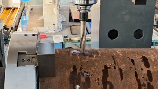
De test moet beginnen met een bevestigde, veilige klemming. De registratie ervan moet de trommel, de gatlocatie, de steunposities, de kleminstellingen, de boor, de houder, de oversteek, de snelheid, de voeding en de koelvloeistofconditie identificeren.
De meetopstelling moet onderscheid maken tussen beweging over afzonderlijke raakvlakken. Een indicator die is bevestigd aan een steun die meebeweegt met de trommel, kan de beweging van het gehele samenstel missen.2 Geschikte instrumenten hebben stabiele referentiepunten nodig buiten het vermoedelijke bewegende gewricht.
Metingen die gestopt zijn voor en na het snijden kunnen een permanente verschuiving aan het licht brengen. Dynamische verplaatsings- of trillingsmetingen zijn nodig om beweging vast te leggen die verdwijnt nadat de snijlast is verwijderd.
| Testfase | Waarneming om vast te leggen | Wat het bewijsmateriaal kan suggereren |
|---|---|---|
| Spindel draait vóór contact | Trilling bij de spindel of houder | Een probleem met het roterende samenstel kan onafhankelijk van het snijden bestaan |
| Initiële intrede | Trommelverplaatsing, ondersteuningsbeweging en gereedschapsdoorbuiging | Ongelijke aangrijping kan een zwakke opstelling of instabiel gereedschap blootleggen |
| Volledige aangrijping | Voortdurende beweging, belastingsvariatie en spaanafvoer | Support flexibility, tool vibration, or chip congestion needs checking |
| Breakthrough and withdrawal | Sudden movement and any remaining datum shift | The changing load may reveal slip or elastic movement |
Compare equivalent cutting conditions
A support comparison should retain the same tooling and cutting settings wherever practical. Equivalent unmachined hole positions should have comparable wall thickness, entry shape, and support distance.
Sound, video, spindle load, and hole quality provide supporting evidence. None identifies the root cause alone.
Relative slip at the chuck points toward a holding problem. Movement that returns to zero can indicate elastic deflection.3 A stable reading at one location does not exclude local shell vibration elsewhere. The inspection needs enough measurement points to distinguish these responses.
Waarom moeten boortype en instapcondities naast de opspanning worden gecontroleerd?
A secure drum can still experience unstable drilling forces. The drill design, mounting, and entry geometry must be checked before a tool change is judged effective.
Drill type and entry conditions determine the forces applied to the workholding. A curved or uneven surface can load cutting edges unevenly during entry. Drill alignment, overhang, edge condition, feed, and coolant must match the application. A replacement drill needs a documented trial before its benefit can be confirmed.
Define the suspected tooling fault
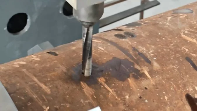
The engineer suspected an off-center U-drill. That description needs a measurable definition. Tool-axis runout, misalignment with the intended hole, and sideways deflection during entry are different conditions.
An indexable drill can have different central and peripheral inserts by design.4 Their appearance alone cannot establish incorrect centering. Runout and alignment should be checked at the points specified for the actual drill and holder.
The proposed crown drill also needs a manufacturer and model identification. The name alone does not establish its cutting geometry or suitability for the drum surface.
| Tooling item | Information needed before the trial | Doel |
|---|---|---|
| Drill model and structure | Cutting diameter, tip or insert design, and application limits | Establishes the correct entry procedure |
| Tool mounting | Holder condition, seating, alignment, and measured runout | Separates mounting faults from cutting deflection |
| Tool length | Required reach and actual overhang | Identifies avoidable flexibility |
| Entry surface | Curvature, local slope, and surface irregularities | Shows how the cutting edges first engage |
| Cutting conditions | Entry feed, full-cut feed, speed, and coolant delivery | Makes the trial reproducible |
Match the entry method to the actual tool
Curved and irregular surfaces can create uneven engagement before the drill reaches full diameter.5 Different drill designs require different entry strategies.
Any feed reduction, pilot operation, or local surface preparation should follow the selected drill’s instructions and the part drawing. A recommendation for one drill design should not automatically be transferred to another.
The replacement drill may require different settings. Those changes must be recorded because the comparison then evaluates the combined tool and process change. In the reported inspection, the replacement trial remained open, so improved stability could not yet be claimed.
Welk bewijs is nodig om te bevestigen dat een retrofit van de opspanning het probleem heeft opgelost?
Completed installation and a running machine leave the original fault unproven. Acceptance needs recorded movement checks and repeatable hole quality under agreed production conditions.
A workholding retrofit is verified by documented modifications, measured control of drum and support movement, and conforming holes across repeated trials. The records must identify comparable cutting conditions and agreed acceptance limits. Installation completion, machine operation, and resolution of the original shaking problem each require separate evidence.
Connect each modification to a measured result
The available records covered installation, commissioning, trial operation, training, and proposed support and hydraulic changes. Re-acceptance with a suitable drill remained outstanding, and final sign-off was incomplete.
A verification report should identify which changes were completed and how they compare with the approved plan. Photographs and installation checks establish the physical arrangement. Loaded measurements and cutting results establish its performance.
| Evidence required | What the record should contain | What it establishes |
|---|---|---|
| Completed modifications | Support locations, plates, connections, lifting arrangements, and applicable hydraulic changes | The installed configuration matches the agreed work |
| Comparable trial conditions | Drum details, hole locations, tooling, clamps, supports, and cutting settings | Results can be compared meaningfully |
| Movement measurements | Drum-to-fixture and support-to-base readings during and after cutting | The setup maintains position within agreed limits |
| Hole inspection | Drawing-based size, position, orientation, and surface checks | The process produces acceptable features |
| Repeated trials | Results across representative positions and repeated cycles | The improvement is consistent within the tested conditions |
| Acceptance decision | Recorded limits, results, remaining issues, and sign-off | The conclusion has a defined basis |
Verify the claimed operating range
A successful hole close to a support may not represent a hole farther along the drum. Trials should include positions that previously showed shaking and other demanding locations within the agreed operating range.
The same principle applies to drum diameters. An adjustable support arrangement needs verification for the sizes covered by the acceptance claim.
If workholding and tooling change together, successful results support acceptance of the combined configuration. They do not isolate the contribution of either change. Without a comparable earlier baseline, the report can establish current performance but cannot quantify the improvement.
The conclusion should state the tested conditions, measured results, and remaining limits. In this case, the supplied records support a troubleshooting and re-inspection plan. They do not yet establish that the original shaking was eliminated.
Conclusie
Boiler drum shaking needs separate checks of workholding movement and cutting vibration. A retrofit is proven through measured stability and repeatable hole quality under documented conditions.
-
"Dynamic Screw Lead Accuracy Measurement – PMC", https://pmc.ncbi.nlm.nih.gov/articles/PMC11548596/. Geometric dimensioning and tolerancing principles show that out-of-roundness and diameter variation alter contact points between cylindrical workpieces and V-supports, shifting the effective center position and potentially creating unstable support conditions. Evidence role: mechanism; source type: education. Supports: How cylindrical form deviations influence support contact and positioning. ↩
-
"Development of a metrology frame to improve the positioning accuracy …", https://www.nist.gov/publications/development-metrology-frame-improve-positioning-accuracy-micromeso-scale-machine-tools. Metrology standards establish that displacement measurements require a reference frame independent of the moving system; sensors mounted to components that move with the measured object cannot detect motion of the entire assembly relative to external references. Evidence role: general_support; source type: education. Supports: The requirement for measurement references to be independent of the measured system. ↩
-
"Effect of machining fixture design parameters on workpiece …", https://pure.psu.edu/en/publications/effect-of-machining-fixture-design-parameters-on-workpiece-displa. Mechanical engineering analysis distinguishes between permanent displacement indicating interface slip or plastic deformation, and recoverable displacement indicating elastic deflection; this distinction is fundamental to diagnosing whether workholding failures involve inadequate clamping force or insufficient structural rigidity. Evidence role: mechanism; source type: education. Supports: How displacement characteristics distinguish between clamping slip and elastic deflection. ↩
-
"Indexable Insert type Drill SumiDrill GDX series | SUMITOMO …", https://www.sumitool.com/en/products/cutting-tools/drills/gdx.html. Modern indexable drill designs commonly employ different insert geometries for central and peripheral positions to optimize cutting conditions across the drill diameter, with center inserts handling lower cutting speeds and peripheral inserts managing higher speeds and chip evacuation. Evidence role: general_support; source type: education. Supports: The use of different insert types in indexable drill designs. ↩
-
"Drill-Point Geometry, Thrust Force, Feed Work, and Hole Diameter – PMC", https://pmc.ncbi.nlm.nih.gov/articles/PMC13665967/. Drilling process mechanics establish that surface curvature and irregularities cause cutting edges to engage progressively rather than simultaneously, with the resulting time-varying forces potentially causing tool deflection and vibration until the drill achieves stable full-diameter engagement. Evidence role: mechanism; source type: education. Supports: How surface irregularities affect the sequence of cutting edge engagement. ↩

Chris Lu
Met meer dan tien jaar praktijkervaring in de werktuigmachine-industrie, vooral met CNC-machines, ben ik er om je te helpen. Of je nu vragen hebt naar aanleiding van dit bericht, begeleiding nodig hebt bij het selecteren van de juiste apparatuur (CNC of conventioneel), aangepaste machineoplossingen onderzoekt of klaar bent om een aankoop te bespreken, aarzel niet om contact met mij op te nemen. Laten we de perfecte bewerkingsmachine voor uw behoeften vinden.