

Why Is the Hole Entrance Oversized on a CNC Drilling Machine?
An oversized entrance can spoil a fit even when the deeper bore is correct. The investigation should identify where enlargement starts and how the drill enters.
The hole entrance becomes oversized when the drill moves or cuts unevenly before stable guidance develops. Mismatched spotting geometry, runout, unequal cutting edges, unsuitable entry feed, and chip damage during re-entry can cause bell-mouthing. The first check is whether enlargement extends below the intended chamfer.
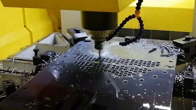
A larger circle at the top of a hole does not reveal how the wall was formed. A planned chamfer removes material, a burr adds material at the edge, and a bell mouth enlarges the bore itself. The drawing and a depth-based inspection establish which feature needs correction before another hole is drilled.
How Can a Bell Mouth Be Distinguished from an Intentional Chamfer or Burr?
Similar-looking entrance features need different corrections. Removing more material can conceal the evidence, so the drawing and bore profile should be checked first.
A bell mouth enlarges the bore below the intended entrance feature. A chamfer has a specified angle and size. A burr projects from the edge and can interfere with measurement. The distinction comes from the drawing and wall dimensions at controlled depths, rather than entrance appearance alone.
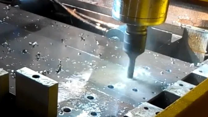
The wall profile reveals the difference
A bell mouth is a flared region that returns toward the normal bore diameter farther inside the hole. It can surround the whole entrance or be stronger on one side. Symmetry alone cannot establish whether the feature is acceptable.
An intentional chamfer has a defined relationship to the bore and part surface. Its angle and size should match the drawing. An unintended flare can exist beneath an otherwise correct chamfer.
| Feature | Location of the material change | Inspection clue |
|---|---|---|
| Bell mouth | Material removed from the bore near the entrance | Bore diameter decreases below the enlarged region |
| Intentional chamfer | Specified bevel between the face and bore | Angle and size match the drawing |
| Burr | Excess material projecting from the edge | Irregular lip or flange affects contact |
| Chamfer with underlying bell mouth | Bevel plus an enlarged bore below it | Correct bevel dimensions but incorrect bore profile |
Measurements need controlled contact depths
The inspector should compare the bore near the entrance, below the affected region, and farther down. The near-entrance reading must account for the specified chamfer and the measuring instrument’s contact geometry.
A pin gauge alone cannot describe how diameter changes with depth1. A suitable bore gauge or profile inspection can establish the extent of the flare.
Loose chips and burrs can distort readings. Any deburring should follow the permitted edge treatment, and the bore should then be measured again. A larger chamfer may hide a flare visually without restoring the required cylindrical length.
How Should Spot-Hole Angle and Diameter Be Matched to the Main Drill?
An unsuitable spot can load the drill unevenly at first contact. Matching its geometry to the main drill helps prevent unstable entry and damaged cutting edges.
When spotting is required, the spot’s included angle should generally be slightly greater than the main drill’s point angle. An equal angle may be acceptable under the tool supplier’s guidance. Spot diameter and depth must suit the drill design; shallow locating spots and deep-hole pilot holes require different dimensions.
The first contact should suit the drill point
A spot with a smaller included angle can bring the outer portions of the drill lips into contact before the central point2. That contact can cause unstable loading and edge damage, especially with carbide drills3.
Common angle pairings provide useful examples.
| Main drill point | Suitable spotting example | Intended contact |
|---|---|---|
| 118° HSS or cobalt drill4 | 120° spot drill | Central point enters first |
| 135°–140° carbide drill | 142° spot drill | Point enters before the outer lip regions |
| Special drill geometry | Supplier-specified preparation | Contact matches the drill’s design |
These pairings do not establish the correct preparation for every drill. The main drill’s application instructions should determine whether spotting is needed.
Spot diameter means the cavity actually produced
The spot drill’s nominal diameter and the diameter of the shallow spot are different dimensions. A larger spot drill can produce a smaller locating spot through limited penetration.
The required spot diameter depends on point geometry and the intended first contact. A fixed fraction of the main drill diameter cannot define every suitable setup. An excessively deep spot can change engagement or leave an unintended entrance bevel.
A dedicated spotting drill also differs from a center drill intended to produce a center-support feature5. Their geometries should be checked before substitution.
A cylindrical pilot hole for a long drill provides guidance along its wall. Its diameter, clearance, depth, and bottom angle should follow the matched drill system. Shallow-spot diameter ratios should not be transferred to that pilot hole.
How Should Entry Feed Be Matched to the Drill and Workpiece Surface?
Heavy entry can deflect a drill, but an extremely light feed can cause rubbing. The correct setting depends on the drill and its initial contact.
Entry feed should follow the drill supplier’s data for the material and surface condition. Flat, rigid entry may permit normal feed. Inclined or uneven entry often needs a reduced feed until engagement becomes stable. Excessively low feed, dwell, and poor rigidity can also worsen the entrance.
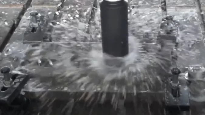
Surface condition changes how the drill engages
A flat surface perpendicular to the drill axis allows more balanced contact. An inclined or curved surface can load one cutting edge before the other. A long drill then has more opportunity to bend sideways.
A reduced entry feed can limit that initial load. The correct reduction depends on the drill type, surface angle, and overhang. A permitted spotface or matched pilot may provide a better entry condition on difficult surfaces.
| Entry condition | Feed approach | Supporting check |
|---|---|---|
| Flat, perpendicular surface and rigid setup | Recommended entry feed for the drill | Runout and cutting-edge condition |
| Inclined or uneven surface | Supplier-specified reduced entry feed | Surface-angle limits and drill length |
| Entry through a prepared spot | Feed matched to the contact geometry | Spot angle, diameter, and alignment |
| Long drill entering a pilot | Drill-system entry procedure | Pilot clearance and alignment |
| Rubbing or unstable chip formation | Review feed within the recommended range | Edge sharpness and coolant delivery |
Feed per revolution and feed per minute need separate checks
For drilling, feed speed equals feed per revolution multiplied by spindle speed:
F (mm/min) = fn (mm/rev) × n (rev/min)6
A spindle-speed change therefore changes feed per revolution if the programmed feed per minute remains fixed.
A larger drill may require lower rpm at the same cutting speed, but its recommended feed per revolution may be higher. Material hardness and drill diameter alone do not justify a universal feed value.
The operator should avoid unnecessary pauses while the rotating drill contacts the entrance. Entry trials should also verify clamping, overhang, runout, and lip symmetry. A feed adjustment cannot restore a damaged or incorrectly ground point.
What Should Be Checked If the Bell Mouth Appears Only After Peck Drilling?
An entrance that enlarges during repeated pecks suggests a re-entry problem. The cycle, chips, and drill condition need comparison before another parameter reduction.
A bell mouth appearing only after peck drilling calls for checks of chip clearance, rapid-to-feed transitions, re-entry alignment, and drill margin or outer-corner damage. Runout, clamping, and drill symmetry also matter. The investigation should establish whether the flare exists after initial penetration or grows during later returns.
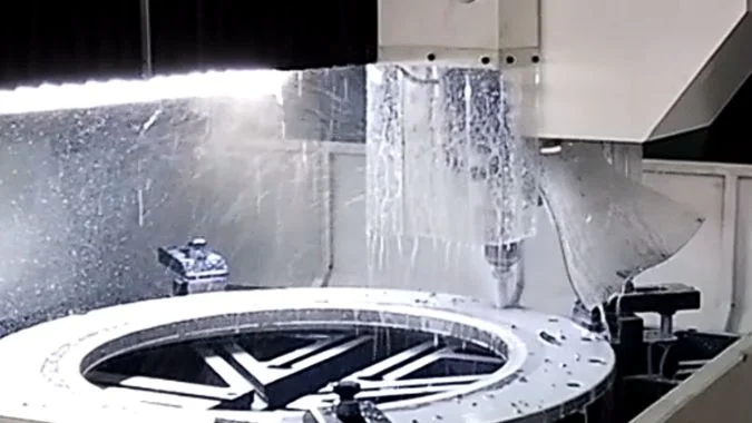
The first cut and later returns provide different evidence
A controlled test on comparable holes can establish when enlargement develops. A flare already present after initial penetration points toward entry geometry, point condition, or setup stability.
An entrance that grows after repeated returns directs attention to the additional motions and chip contact. Full-retract cycles carry the drill through the entrance again. Short-retract chip-breaking cycles create a different contact history.
| Check | Evidence to look for | Possible effect |
|---|---|---|
| Chip evacuation | Packed flutes, trapped chips, or scoring | Chips rub or are cut again near the entrance |
| Rapid-to-feed transition | Unexpected contact before feed resumes | Impact damages the point or destabilizes the drill |
| Margins and outer corners | Chipping, deposits, or uneven wear | Guidance and wall contact become unstable |
| Holder and spindle | Poor seating, looseness, or excessive runout | Repeated wall contact enlarges the entrance |
| Drill lips and chisel edge7 | Unequal lips or incorrect point grinding | Unbalanced cutting forces |
| Guide bushing, if fitted | Wear, looseness, or misalignment | The drill loses reliable guidance |
The cycle must suit the drill system
The programmer should verify actual retract distances and the clearance above the previous cutting depth. The rapid approach must transition to cutting feed before the drill reaches uncut material. Trapped chips can make contact occur earlier than expected.
Coolant needs sufficient flow at the cutting zone, and through-coolant passages should remain clear. The inspection should also check whether chips are carried back into the hole.
Peck depth and retract style should follow the drill’s application guidance. Some through-coolant carbide drills8 are designed for continuous drilling within their rated depth. Adding frequent full retracts can introduce unnecessary re-entry events.
The next trial should change one identified factor and compare entrance diameter at the same depths. Growing damage across a production batch also calls for a review of tool wear and replacement timing.
Conclusion
An oversized entrance needs profile verification, matched spotting geometry, stable entry feed, and controlled peck re-entry. The correction should restore the required bore below the specified edge treatment.
-
"Bore Gauge vs Pin Gauge: Choosing the Right Measuring …", https://www.lfc.com.sg/blog/detail/bore-gauge-vs-pin-gauge. Pin gauges provide go/no-go verification at a single depth but cannot capture diameter variation along the bore axis, as they measure only the minimum diameter that permits gauge entry rather than the complete cylindrical profile. Evidence role: mechanism; source type: education. Supports: the measurement limitations of pin gauges for bore profiling. ↩
-
"Spot Drilling: The First Step to Precision Drilling", https://www.harveyperformance.com/in-the-loupe/choosing-spot-drill/. When a spot drill’s included angle is smaller than the main drill’s point angle, the drill’s outer cutting edges contact the workpiece before the chisel edge, potentially causing unstable loading and premature wear. Evidence role: mechanism; source type: education. Supports: the geometric principle that spot drill angle affects the sequence of drill point contact. Scope note: This describes the geometric relationship; optimal angle pairings vary by drill design and manufacturer recommendations. ↩
-
"Tungsten carbide", https://en.wikipedia.org/wiki/Tungsten_carbide. Carbide drills, typically made from tungsten carbide, offer superior hardness and heat resistance compared to high-speed steel, enabling higher cutting speeds and longer tool life, but are more brittle and sensitive to impact loading and improper entry conditions. Evidence role: general_support; source type: education. Supports: the material properties and performance characteristics that distinguish carbide drills from high-speed steel drills. ↩
-
"Consensus on drill bit angles for machinists", https://www.reddit.com/r/Machinists/comments/1bvjei4/this_feels_like_a_dumb_question_but_im_curious/. The 118° point angle has been widely adopted as a standard geometry for general-purpose twist drills in softer materials, while 135° angles are common for harder materials and self-centering applications. Evidence role: general_support; source type: institution. Supports: that 118° is a conventional point angle for general-purpose HSS and cobalt steel twist drills. Scope note: Standards vary by region and manufacturer; specific applications may require different angles. ↩
-
"Spot drill or center drill? : r/Machinists", https://www.reddit.com/r/Machinists/comments/1e3h66m/spot_drill_or_center_drill/. Center drills feature a combination drill and countersink geometry designed to create conical recesses for lathe center support, whereas spotting drills have a rigid, short-flute design optimized solely for creating shallow starting divots that guide subsequent drilling operations. Evidence role: definition; source type: education. Supports: the functional and geometric differences between spotting drills and center drills. ↩
-
"Speeds and Feeds", https://web.mae.ufl.edu/designlab/Advanced%20Manufacturing/Speeds%20and%20Feeds/Speeds%20and%20Feeds.htm. The feed rate in machining operations is calculated as the product of feed per revolution and spindle speed, a fundamental relationship used across turning, milling, and drilling processes to convert rotational parameters into linear cutting motion. Evidence role: mechanism; source type: education. Supports: the mathematical relationship between feed rate, feed per revolution, and spindle speed in machining. ↩
-
"How the geometry of a drill influences tool life and hole …", https://cuttingtools.ceratizit.com/us/en/machining-know-how/holemaking-and-boring/application-and-technical-info/drill-geometry.html. The chisel edge is the transverse cutting edge formed at the intersection of the two flank surfaces at the drill point center; it performs a scraping rather than cutting action and contributes to thrust force, with its geometry significantly affecting drill penetration and centering behavior. Evidence role: definition; source type: education. Supports: the definition and function of the chisel edge in drill point geometry. ↩
-
"Through Coolant Drill: Enhances Drilling Efficiency", https://guesstools.com/through-coolant-drill-enhances-drilling-efficiency/. Through-coolant drills incorporate internal passages that deliver cutting fluid directly to the cutting edges, improving chip evacuation and heat removal compared to external coolant delivery, particularly in deep-hole drilling applications. Evidence role: general_support; source type: research. Supports: the design and operational advantages of through-coolant drill technology. Scope note: Performance benefits depend on coolant pressure, flow rate, and specific drill geometry. ↩

Chris Lu
Leveraging over a decade of hands-on experience in the machine tool industry, particularly with CNC machines, I'm here to help. Whether you have questions sparked by this post, need guidance on selecting the right equipment (CNC or conventional), are exploring custom machine solutions, or are ready to discuss a purchase, don't hesitate to CONTACT Me. Let's find the perfect machine tool for your needs.