

Why Do Chatter Marks Appear on Long Lead Screws During Whirling?
Chatter marks can damage thread finish and shorten insert life. A useful investigation starts with workpiece support, cutter-ring condition, and the cutting settings used at the affected position.
Chatter marks appear when vibration between the cutter ring and a long lead screw disrupts cutting. A flexible unsupported span, uneven insert engagement, worn components, or unstable settings can trigger the problem. Repeated cutting impacts can excite vibration, and regenerative chatter can amplify it.
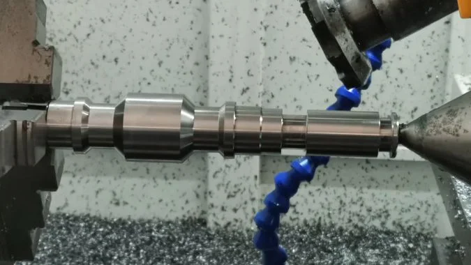
A long lead screw may look rigid between its supports, but its resistance to bending changes along the cutting path. The rotating cutter ring also leaves a normal surface pattern during stable cutting. A useful diagnosis starts by comparing that expected texture with the deeper waviness that appears as vibration grows.
How Can Chatter Marks Be Distinguished from the Normal Whirling Surface Pattern?
Normal cutter marks can resemble vibration damage. Misreading them can lead to unnecessary adjustments, so the surface pattern needs comparison with sound, location, and cutting behavior.
Chatter marks usually add pronounced waviness, uneven mark depth, or bands of poor finish to the expected whirling texture. Normal marks are more consistent under unchanged conditions. Periodic spacing alone cannot identify chatter because stable whirling also leaves repeating marks. A speed trial provides supporting evidence.
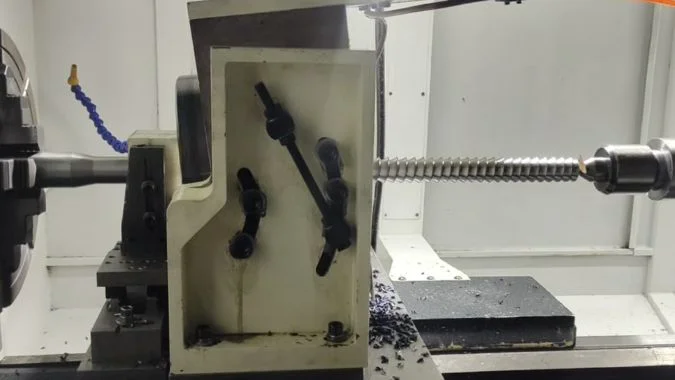
Normal whirling leaves its own repeating pattern
Each insert removes material during part of the cutter ring’s rotation1. Successive cuts form an envelope, so a stable process can leave fine scallops or facets.
Their spacing depends on the cutting geometry and the relationship between cutter-ring speed and workpiece rotation. A regular pattern does not automatically mean vibration.
| Observation | Normal whirling texture | Suspected chatter or vibration damage |
|---|---|---|
| Mark depth | Consistent under stable conditions | Deeper waviness or changing depth |
| Distribution along the screw | Predictable for the setup | Often worse in flexible spans |
| Cutting sound | Steady for the operation | New squealing, pulsing, or rattling |
| Surface measurements | Consistent finish and profile | Increased waviness or local profile error |
| Response to a speed change | Texture spacing may change | Waviness and vibration may decrease sharply |
A speed trial needs more than a spacing comparison
The operator should inspect the stopped, cleaned workpiece under consistent lighting and magnification. A surface trace can help distinguish fine texture from larger undulations2.
A short trial at a small, approved speed change can reveal a more stable cutting condition. The comparison should use similar support distance, allowance, and insert condition.
A spacing change alone remains inconclusive. Stronger evidence combines reduced waviness, quieter cutting, and lower vibration. Periodic forcing from runout can also leave regular marks3, so a surface photograph alone cannot establish regenerative chatter.
Why Does Chatter Become Worse Farther from a Workpiece Support?
A screw may cut cleanly near a support and vibrate farther away. The changing unsupported span needs checking before the entire cutting program is revised.
Chatter often worsens farther from a support because the cutting point becomes easier to deflect under changing forces. Support spacing and bending modes determine the local response. A longer unsupported span can increase vibration, and a cutting point near a vibration antinode can show particularly strong marks.
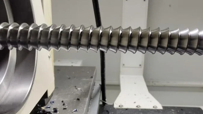
The local span controls resistance to bending
A long lead screw has limited bending stiffness compared with a short workpiece of the same diameter4. The cutting force acts at a moving position, so the resistance at the cutting point changes during the operation.
A simple cantilever model illustrates the sensitivity: deflection under the same end load increases with the cube of unsupported length5. A screw held between centers has different boundary conditions, so that exact relationship should not be applied to every setup.
The practical concern is the effective unsupported span around the cutting point. A distant chuck or center may provide secure location but insufficient local support.
| Support condition | Likely effect | Useful check |
|---|---|---|
| Long distance from the nearest effective support | Greater bending under cutting force | Support position relative to the cut |
| Wide span between two supports | Strong response within the span | Where marks appear along the screw |
| Loose or worn center | Movement at the support | Contact condition and alignment |
| Excessive tailstock pressure | Possible bowing or preload distortion | Specified force and thermal allowance |
| Poorly adjusted steady or follow rest | Unstable or distorted support | Contact, alignment, and support surface |
Support must remain effective during travel
A suitable steady rest or follow rest can shorten the flexible span6. Its contact surfaces and position must suit the screw geometry.
Greater clamping force alone may introduce bending. The setup should provide secure location without forcing the shaft away from its intended axis.
A record of mark severity against cutting position helps identify a support-related pattern. The strongest vibration may occur within a span, rather than increasing steadily from one end to the other.
How Should Whirling Cutter Ring Runout and Insert Condition Be Checked?
Uneven insert engagement can excite a flexible screw. Checking the assembled cutter ring and its cutting edges helps identify repeated load differences before parameters are changed.
Cutter-ring runout should be measured at the manufacturer’s specified reference surfaces, and installed cutting-edge positions need a separate check. The inspection should cover mounting cleanliness, insert seating, clamping, wear, and chipping. Axial face runout and spindle axial play require different checks.
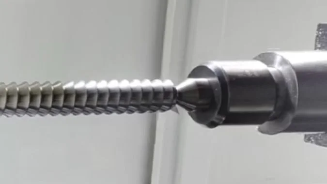
Body runout and cutting-edge position are separate measurements
The inspection should follow the machine’s stopped service procedure. A rigid indicator setup and slow manual rotation can reveal radial or face variation at the specified surfaces.
A true-running outside diameter does not establish that every insert tip occupies its correct position. An insert can sit on trapped debris, tilt in its pocket, or project farther into the cut.
| Inspection point | Evidence to look for | Why it matters |
|---|---|---|
| Cutter-ring mounting interface | Dirt, damage, or incomplete seating | The whole ring can mount incorrectly |
| Radial and face reference surfaces | Variation beyond the specified limit | Ring rotation may be inaccurate |
| Installed cutting edges | Incorrect projection or orientation | Inserts may engage unevenly |
| Pocket, clamp, and screw | Trapped chips, damage, or poor retention | An insert can shift during cutting |
| Cutting edges | Uneven wear, chipping, or deposits | Cutting forces can vary between inserts |
The tool supplier’s setting fixture or measuring procedure should establish the correct cutting-edge positions. Generic milling runout limits should not replace the cutter ring’s requirements.
Insert wear needs comparison across the set
A wider flank wear band on one matching insert can suggest heavier engagement or rubbing. Chipped corners, notches, and deposits need investigation because they change the effective cutting geometry.
A fresh insert can address edge damage, but the pocket and mounting condition still need verification. Repeated damage at the same pocket strengthens the case for a local seating or position problem.
A rotating face measurement indicates face runout. Axial play needs the spindle manufacturer’s separate checking procedure.
Vibration during approved idle running points toward rotating-system or machine issues. Vibration that grows mainly under cutting load also calls for checks of support stiffness and engagement.
How Should Cutting Speed and Feed Be Adjusted to Reduce Chatter?
Parameter changes can reduce marks, but uncontrolled feed changes can also affect the thread. Trials need a clear speed reference and synchronized motion.
Cutter-ring speed should be adjusted in controlled steps to find a stable cutting range. Feed may need increasing when chips are too thin and the edges rub, but excessive load calls for a different correction. Workpiece rotation and axial travel must remain synchronized to preserve the specified thread lead.
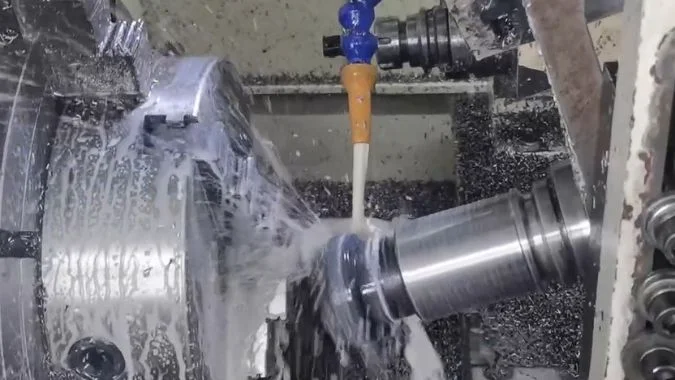
Cutter-ring speed and workpiece speed need separate records
The cutter ring rotates rapidly, and the workpiece turns more slowly. A record that lists only “spindle speed” can leave the trial unclear.
A speed change alters the timing of insert engagement7. Either a higher or lower cutter-ring speed may produce a more stable result. The response depends on the assembled system and its cutting conditions.
| Trial adjustment | Condition that supports it | What needs monitoring |
|---|---|---|
| Small cutter-ring speed change | Vibration changes strongly with speed | Waviness, sound, wear, and cutting load |
| Feed increase within supplier guidance | Chip thickness is too low and rubbing occurs | Force, finish, and insert damage |
| Lower engagement through an approved pass strategy | The existing cut overloads the flexible setup | Profile accuracy and remaining allowance |
| Support correction before another trial | Marks track a flexible span | Local vibration and shaft alignment |
The trials should compare similar positions along the screw. A cut near a support and one near midspan can behave differently even at identical settings.
Feed must preserve the thread’s motion relationship
The axial travel per workpiece revolution must match the programmed lead8. A production-feed change should use the control’s intended synchronized settings.
The record should distinguish cutter-ring rpm, workpiece rpm, axial feed, and any supplier-defined chip-load value. The cutter and machine documentation should establish the correct units and working range.
A feed increase can help an underfed edge cut instead of rub. It can also increase cutting force, so the result needs verification on the supported workpiece.
Programmed speed variation requires a machine-supported strategy that maintains the required synchronization. Its amplitude and timing need validation for the application.
Insert condition and support rigidity should be corrected first. A successful trial should then confirm surface finish, thread profile, and lead accuracy across the working length.
Conclusion
Chatter control starts with distinguishing vibration damage from normal texture. Effective support, accurate insert positioning, and controlled speed and synchronized-feed trials help restore consistent thread quality.
-
"Thread Whirling", https://ntkcuttingtools.com/products/threading/tw/. In thread whirling, multiple inserts mounted in a rotating cutter ring engage the workpiece sequentially, with each insert removing material during a portion of the ring’s rotation cycle to progressively form the thread profile. Evidence role: mechanism; source type: education. Supports: the intermittent engagement pattern of inserts in a rotating whirling head. ↩
-
"The vibrations of texture – PMC – NIH", https://pmc.ncbi.nlm.nih.gov/articles/PMC2074877/. Surface profilometry separates roughness (fine texture from tool geometry) from waviness (longer-wavelength undulations) through filtering, enabling quantitative distinction between normal machining marks and vibration-induced surface defects. Evidence role: general_support; source type: research. Supports: the use of surface measurement techniques to distinguish between different spatial frequencies of surface features. ↩
-
"What Is Runout in Machining? Causes and How to Reduce It", https://taigtools.com/blog/runout-in-machining/. Geometric runout in rotating tooling or workpieces creates periodic variation in cutting conditions that can produce regular surface marks at frequencies related to the rotation rate, independent of dynamic instability. Evidence role: mechanism; source type: research. Supports: the mechanism by which geometric runout produces periodic surface marks. ↩
-
"Bending stiffness", https://en.wikipedia.org/wiki/Bending_stiffness. Bending stiffness decreases as workpiece length increases for a given diameter, with the effective stiffness at a point depending on the span configuration and boundary conditions. Evidence role: mechanism; source type: education. Supports: the inverse relationship between workpiece length and effective bending stiffness. ↩
-
"BEAM DEFLECTION FORMULAS", https://home.engineering.iastate.edu/~shermanp/STAT447/STAT%20Articles/Beam_Deflection_Formulae.pdf. For a cantilever beam under end load, deflection is proportional to the cube of the beam length according to classical beam theory (δ = PL³/3EI, where P is load, L is length, E is elastic modulus, and I is moment of inertia). Evidence role: mechanism; source type: education. Supports: the mathematical relationship between cantilever beam deflection and unsupported length. Scope note: This relationship applies to idealized cantilever conditions; workpieces supported between centers have different boundary conditions as the article notes. ↩
-
"Adjusting the Stiffness of Supports during Milling of a Large …", https://pmc.ncbi.nlm.nih.gov/articles/PMC9318714/. Steady rests and follow rests provide intermediate support points that reduce the effective unsupported span of long workpieces, increasing local stiffness and reducing susceptibility to vibration during machining operations. Evidence role: general_support; source type: education. Supports: the use of intermediate supports to reduce effective span and improve stability when machining long workpieces. ↩
-
"Chatter Stability of Machining Operations", https://academy.cba.mit.edu/classes/computer_machining/chatter.pdf. Cutting speed determines the frequency of tool engagement and the phase relationship between successive cuts, which can shift the system away from resonant conditions or disrupt the regenerative feedback mechanism that sustains chatter. Evidence role: mechanism; source type: research. Supports: how cutting speed changes affect the phase relationship between successive cutting passes and system natural frequencies. ↩
-
"Influence of Processing Parameters on the Thread and Spline …", https://pmc.ncbi.nlm.nih.gov/articles/PMC6566950/. In thread cutting operations, the thread lead (axial advance per revolution) is determined by the ratio of axial feed velocity to workpiece rotational speed, requiring precise synchronization to achieve the specified thread pitch. Evidence role: mechanism; source type: education. Supports: the kinematic relationship between feed rate and rotation that determines thread lead accuracy. ↩

Chris Lu
Leveraging over a decade of hands-on experience in the machine tool industry, particularly with CNC machines, I'm here to help. Whether you have questions sparked by this post, need guidance on selecting the right equipment (CNC or conventional), are exploring custom machine solutions, or are ready to discuss a purchase, don't hesitate to CONTACT Me. Let's find the perfect machine tool for your needs.