

Come è possibile ridurre le bave durante la lavorazione dei profili in alluminio?
Le bave sui profili in alluminio aggiungono lavoro manuale e possono ostacolare l'assemblaggio. Un processo più pulito inizia con utensili affilati, condizioni di taglio controllate e un migliore supporto dei bordi.
Le bave sui profili in alluminio possono essere ridotte con utensili affilati, una geometria di taglio adeguata, avanzamenti e velocità bilanciati, una lubrificazione efficace e percorsi utensile stabili. I bordi di uscita supportati e le passate di finitura controllate aiutano a limitare lo strappo. La smussatura o un altro processo di sbavatura adatto rimuove le bave rimanenti.
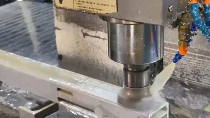
Un profilo può uscire dalla macchina con facce pulite ma bordi irregolari attorno ai singoli elementi. Tali bordi rivelano dove il processo di taglio richiede attenzione. Un taglio di sega, un foro praticato e una fresata creano condizioni diverse. Il primo passo utile è identificare quale operazione lascia la bava e dove appare.
Quali operazioni di lavorazione dei profili hanno maggiori probabilità di lasciare bave?
Alcune operazioni richiedono una maggiore pulizia dei bordi rispetto ad altre. La sbavatura non pianificata aumenta i tempi di movimentazione, pertanto l'ispezione dovrebbe iniziare con tagli di sega, fori, filettature e fresate.
La segatura e la foratura sono fonti comuni di bave sui profili in alluminio, specialmente in corrispondenza dei bordi di uscita non supportati. Anche la maschiatura e la fresatura di asole lasciano bave attorno a pareti sottili, aperture filettate e bordi delle asole. Le condizioni dell'utensile, la lubrificazione e il supporto locale determinano quale operazione crea il problema maggiore.
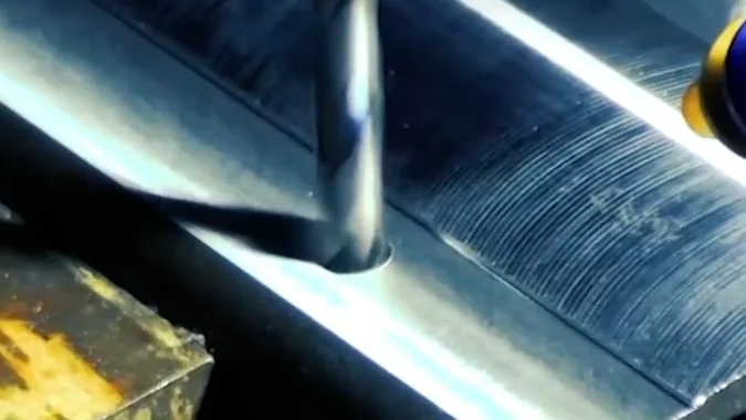
I tagli di sega e i fori praticati meritano controlli precoci
Una lama può lasciare un bordo irregolare attorno alla sezione trasversale tagliata. Denti smussati, geometria della lama non idonea, scarsa lubrificazione e impostazioni di taglio errate possono contribuire al problema. L'alluminio che si attacca a un dente ne altera l'azione di taglio1, quindi la lama inizia a spingere o strappare il materiale invece di separarlo in modo netto.
La foratura lascia spesso la sua bava più visibile al momento della fuoriuscita. Il materiale rimanente diventa sottile man mano che la punta si avvicina al lato opposto. La forza di taglio può spingere quel materiale verso l'esterno prima che il bordo si separi2.
| Operazione | Posizione comune della bava | Primi punti da ispezionare |
|---|---|---|
| Segatura | Estremità tagliate e pareti di sezioni sottili | Condizione del dente, scelta della lama, lubrificazione e avanzamento |
| Perforazione | Uscita del foro e aperture su pareti sottili | Affilatura della punta, avanzamento in uscita e supporto del pezzo |
| Picchiettatura | Ingressi e uscite di filettatura | Condizioni del maschio, lubrificazione e spessore della parete |
| Fresatura di scanalature | Estremità delle scanalature e bordi superiori o inferiori | Condizioni della fresa, direzione di taglio e rimozione dei trucioli |
Le pareti sottili e le scanalature profonde richiedono maggiore attenzione
La maschiatura può sollevare materiale attorno all'apertura di una filettatura, specialmente in una parete sottile. La fresatura di scanalature può lasciare piccole bave lungo i bordi o bave più grandi nel punto in cui la fresa esce dal materiale.
L'ispezione deve includere le superfici nascoste all'interno del profilo. Le scanalature profonde possono trattenere trucioli sciolti insieme a bave attaccate. Si tratta di problemi diversi: la pulizia rimuove i trucioli sciolti, ma una bava attaccata richiede il taglio o un altro metodo di sbavatura.
Il registro del processo dovrebbe identificare l'operazione e il bordo interessato. Tale dettaglio rende la regolazione successiva più utile rispetto a una nota generica che indica che il pezzo necessita di sbavatura.
In che modo differiscono i bordi di entrata e di uscita nella formazione di bave?
Un ingresso pulito può nascondere un'uscita ruvida. Tale bava nascosta può interferire con l'assemblaggio, pertanto entrambi i lati di ciascuna caratteristica lavorata richiedono attenzione.
Le bave in ingresso sono spesso più piccole perché il materiale circostante supporta il bordo all'inizio del taglio. Le bave in uscita sono spesso più grandi perché il materiale rimanente perde supporto e si piega o si strappa quando l'utensile esce. Le pareti sottili rendono questa differenza particolarmente evidente durante la foratura e la fresatura.
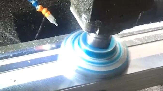
Il supporto del bordo cambia durante il taglio
All'ingresso, il tagliente incontra materiale che solitamente ha un supporto dietro di sé. Un utensile affilato può iniziare a separare il truciolo con una minore flessione del bordo del pezzo.
All'uscita, la sezione rimanente diventa più facile da deformare. L'alluminio può piegarsi formando un labbro prima di separarsi, poiché il materiale è duttile3. Un utensile usurato o un carico di taglio elevato possono aumentare tale deformazione.
Questo schema è comune, ma non è una regola assoluta. Lo spessore locale della parete, la direzione di taglio e la geometria dell'utensile possono cambiare quale bordo presenta la bava più grande.
| Condizione del bordo | Comportamento tipico | Risposta pratica |
|---|---|---|
| Ingresso supportato | Il bordo di solito resiste meglio alla flessione | Mantenere un utensile affilato e un ingresso stabile |
| Uscita non supportata | Il materiale rimanente può piegarsi verso l'esterno | Migliorare il supporto e rivedere il movimento di uscita |
| Sfondamento di pareti sottili | La parete può flettersi prima della separazione | Check local rigidity and breakthrough feed |
| Exit inside a groove | The burr can remain difficult to reach | Plan inspection and deburring access early |
Tool paths should account for the final edge
Process planning should place critical exits near supported sections where the profile geometry allows. A controlled feed reduction near breakthrough can help when cutting force is pushing a thin edge outward4. The reduction still needs to preserve a clean cutting action.
Lubrication also matters because aluminum buildup changes the effective cutting edge5. A suitable tool geometry and reliable fluid delivery help maintain a cleaner cut.
Any remaining edge break should follow the drawing. A small chamfer can remove a burr, but its size must suit the required fit and edge condition.
Come dovrebbero essere rivisti gli avanzamenti e le velocità quando le bave aumentano?
Burr growth can turn a stable job into repeated rework. Tool checks and controlled parameter trials help identify the cause before more parts need cleanup.
A feed reduction is worth testing when excessive cutting force causes burrs, but tool wear and lubrication should be checked first. Cutting speed then needs review against heat, adhesion, and tool condition. Lower settings are useful only when they improve cutting instead of increasing rubbing.
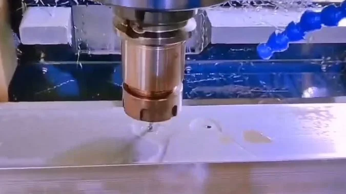
Tool condition comes before parameter changes
A sudden increase in burrs can indicate a dull edge, chipped tooth, or aluminum buildup. Lowering the feed cannot restore the geometry of a damaged tool. The operator should inspect the cutting edges and replace or resharpen worn tools as appropriate.
The coolant or lubrication system also needs checking at the cutting point. A running pump does not prove that fluid reaches the tool. Chips packed around the cutter can block delivery and damage the machined surface.
Feed and speed need separate, controlled trials
A lower feed can reduce force when the tool is pushing material outward6. The trial should use a small change and compare the same feature under otherwise similar conditions.
Cutting speed should then be reviewed against the observed problem. A reduction may help when excessive heat or rapid wear is present7. A blanket reduction is less useful when adhesion or rubbing is the main issue.
| Observation | First action | Parameter review |
|---|---|---|
| Burrs rise suddenly during a batch | Inspect wear and aluminum buildup | Restore tool condition before changing settings |
| A thin exit edge bends outward | Check support and cutting load | Test a controlled reduction near exit |
| Heat and tool wear rise together | Check lubrication and engagement | Review whether cutting speed is excessive |
| The surface looks smeared | Inspect adhesion and cutting geometry | Check whether the tool is rubbing |
| Chips collect in the slot | Restore chip removal | Review cut depth, width, and feed together |
The feed setting must suit the tool, spindle speed, and amount of material engaged. A finishing cut still needs to form a chip. An extremely low feed or shallow engagement can make the edge rub instead8.
The operator should record each change and inspect burr size, surface finish, and dimensions. A setting is useful only when it improves the part consistently.
Quando può una passata di finitura ridurre le bave nelle fresate?
A rough slot edge can survive an extra pass. Finishing helps when the tool removes a controlled allowance with stable support and a suitable cutting direction.
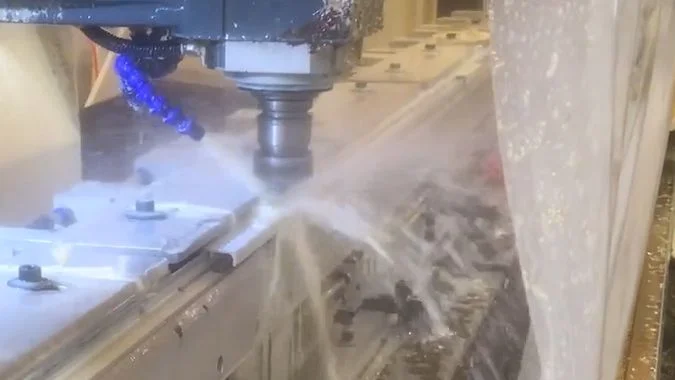
A finishing pass can reduce slot burrs when roughing leaves a small, consistent allowance and a sharp cutter removes it under stable conditions. Climb milling is often suitable for supported slot walls. Remaining top or bottom edge burrs may still need a separate chamfering or deburring operation.
A finishing pass needs material to cut
The roughing path should leave a controlled allowance on the surfaces that need finishing. The finishing cutter can then remove that material with a lighter, more consistent load.
An extra pass over an already finished surface may not remove an attached edge burr. The cutter may miss its root or simply bend the lip. The finishing path needs to engage the affected area without taking the slot outside its dimensional limits.
| Slot condition | Likely value of a finishing pass | Process requirement |
|---|---|---|
| Rough walls with a consistent allowance | The pass can improve the wall and reduce edge tearing | Sharp cutter and controlled engagement |
| Burrs near the tool exit | A revised finishing path can reduce their formation | Supported exit and suitable feed |
| Burrs along a top or bottom edge | Wall finishing alone may leave them attached | Separate edge treatment where required |
| Flexible walls or packed chips | Another pass can repeat the defect | Better support and chip removal first |
Climb milling can improve the finishing cut
In peripheral climb milling, chip thickness starts larger and decreases toward the end of engagement9. This cutting action can help produce cleaner edges on aluminum10.
The machine, fixture, and profile must remain stable under the cutting force. A finishing path should account for thin walls, internal corners, and changes in engagement. Climb milling deserves consideration during both roughing and finishing when the setup supports it.
Separate finishing movements along the slot walls give the programmer more control over cutting direction and the final exit. Chips should clear the slot before they can be cut again or scratch the finished surface.
Remaining burrs need a defined removal step
A chamfering tool can remove small remaining burrs when the drawing allows an edge break11. The operation should follow the final cut that creates the burr.
Other mechanical deburring methods may suit particular part sizes and production volumes. Deep grooves need inspection after cleanup because detached burrs and chips can remain trapped inside the profile.
Conclusione
Sharp tools, balanced cutting settings, supported exits, and controlled finishing passes reduce aluminum profile burrs. Planned deburring and thorough cleaning address what remains.
-
"Effect of Built-Up Edge Formation during Stable State of Wear …", https://pmc.ncbi.nlm.nih.gov/articles/PMC5706177/. Material adhesion to cutting edges, known as built-up edge (BUE) formation, alters effective rake angle and increases cutting forces in aluminum machining, particularly at intermediate cutting speeds where adhesion is most pronounced. Evidence role: mechanism; source type: research. Supports: how material adhesion to cutting edges changes effective tool geometry and cutting mechanics. Scope note: Research typically addresses general BUE mechanisms rather than tooth-specific behavior in sawing operations ↩
-
"Experimental Study of Thrust Force and Torque for Drilling …", https://pubmed.ncbi.nlm.nih.gov/30627838/. During drill breakthrough, thrust force acting on the remaining thin material causes plastic deformation and bending before fracture, with burr size correlating to the ratio of thrust force to remaining material thickness. Evidence role: mechanism; source type: research. Supports: the relationship between drilling thrust force and material deformation at breakthrough. ↩
-
"Tool wear and burr formation during drilling of aluminum …", https://www.sciencedirect.com/science/article/pii/S2214785322001389. Materials with higher ductility, including aluminum alloys, exhibit greater plastic deformation before fracture during cutting, resulting in larger burrs through bending and tearing mechanisms rather than clean shearing. Evidence role: mechanism; source type: research. Supports: how ductility influences burr formation through plastic deformation before fracture. Scope note: Burr size depends on multiple factors beyond ductility, including cutting conditions and tool geometry ↩
-
"Figure 6 – from Burr formation minimization in drilling", https://www.academia.edu/figures/17127970/figure-7-height-of-burr-vs-speed-feed-rate-and-point-angle. Experimental studies demonstrate that reducing feed rate during the final portion of drilling operations decreases thrust force and exit burr height, though the optimal reduction timing and magnitude depend on material thickness and drill diameter. Evidence role: general_support; source type: research. Supports: the effectiveness of feed rate reduction strategies for exit burr control. ↩
-
"Effect of Cutting Fluid on Milled Surface Quality and Tool Life …", https://pmc.ncbi.nlm.nih.gov/articles/PMC10056421/. Effective lubrication reduces aluminum adhesion to cutting tools by lowering interface temperature and providing a boundary layer that inhibits metal-to-metal contact, thereby minimizing built-up edge formation. Evidence role: mechanism; source type: research. Supports: how lubrication reduces aluminum adhesion to cutting tools. Scope note: Effectiveness varies with lubricant chemistry, delivery method, and cutting speed range ↩
-
"Velocità e avanzamenti", https://en.wikipedia.org/wiki/Speeds_and_feeds. Cutting forces increase approximately linearly with feed rate in most machining operations, as feed directly determines uncut chip thickness and therefore the material volume resisting deformation. Evidence role: mechanism; source type: research. Supports: the relationship between feed rate and cutting forces. ↩
-
"Optimizing Cutting Parameters for Enhanced Control of … – PMC", https://pmc.ncbi.nlm.nih.gov/articles/PMC11901140/. Cutting temperature increases with cutting speed due to higher shear rates and reduced heat dissipation time, with tool wear rate typically following an exponential relationship to cutting speed in most tool-material combinations. Evidence role: mechanism; source type: research. Supports: how cutting speed affects heat generation and tool wear rates. Scope note: Optimal speed ranges vary significantly with tool material, workpiece alloy, and cooling method ↩
-
"Estimation of Minimum Uncut Chip Thickness during Precision …", https://pmc.ncbi.nlm.nih.gov/articles/PMC8745993/. When uncut chip thickness falls below a critical value (typically 20-40% of cutting edge radius), material deformation transitions from shearing to ploughing and rubbing, increasing specific cutting energy and surface damage without effective material removal. Evidence role: mechanism; source type: research. Supports: the minimum chip thickness phenomenon and its relationship to rubbing. ↩
-
"Influence of Machining Parameters on Cutting and Chip … – PMC", https://pmc.ncbi.nlm.nih.gov/articles/PMC9502497/. In climb (down) milling, the cutter tooth enters the workpiece at maximum chip thickness and exits at zero, producing a chip that decreases in thickness through the engagement arc, in contrast to conventional (up) milling where chip thickness increases from entry to exit. Evidence role: mechanism; source type: education. Supports: the chip thickness variation pattern in climb milling. ↩
-
"Climb Milling vs. Conventional Milling", https://www.youtube.com/watch?v=galm5_6SUcM. Climb milling generally produces better surface finish and reduced exit burrs in aluminum machining because the cutting action directs forces into the workpiece rather than lifting material, though this advantage requires adequate machine rigidity to prevent chatter. Evidence role: general_support; source type: research. Supports: the edge quality advantages of climb milling in aluminum. Scope note: Benefits depend on machine stiffness, fixturing, and workpiece geometry; unstable setups may perform better with conventional milling ↩
-
"Deburring tool for soft materials: effective alternative to filing?", https://www.facebook.com/groups/769782850345135/posts/1627978804525531/. Chamfering operations effectively remove small to medium burrs while creating a controlled edge break, with process capability depending on burr size relative to chamfer dimensions and consistency of burr location. Evidence role: general_support; source type: research. Supports: the effectiveness of chamfering as a deburring method. Scope note: Effectiveness decreases for large or irregular burrs that exceed the chamfer envelope or vary in position ↩

Chris Lu
Avvalendomi di oltre un decennio di esperienza pratica nel settore delle macchine utensili, in particolare con le macchine CNC, sono qui per aiutarvi. Se avete domande suscitate da questo post, se avete bisogno di una guida per la scelta dell'attrezzatura giusta (CNC o convenzionale), se state esplorando soluzioni di macchine personalizzate o se siete pronti a discutere un acquisto, non esitate a CONTATTARMI. Troviamo la macchina utensile perfetta per le vostre esigenze.