

¿Cómo se pueden reducir las rebabas al mecanizar perfiles de aluminio?
Las rebabas en los perfiles de aluminio añaden trabajo manual y pueden dificultar el montaje. Un proceso más limpio comienza con herramientas afiladas, condiciones de corte controladas y un mejor soporte de los bordes.
Las rebabas en los perfiles de aluminio pueden reducirse con herramientas afiladas, una geometría de corte adecuada, avances y velocidades equilibrados, una lubricación eficaz y trayectorias de herramienta estables. El soporte en los bordes de salida y las pasadas de acabado controladas ayudan a limitar el desgarro. El biselado u otro proceso de desbarbado adecuado elimina las rebabas restantes.
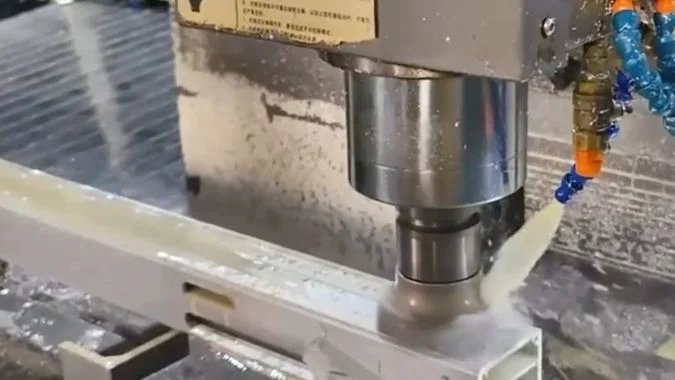
Un perfil puede salir de la máquina con caras limpias y bordes rugosos alrededor de características individuales. Esos bordes revelan dónde el proceso de corte necesita atención. Un corte de sierra, un orificio taladrado y una ranura fresada crean condiciones diferentes. El primer paso útil es identificar qué operación deja la rebaba y dónde aparece.
¿Qué operaciones de mecanizado de perfiles tienen más probabilidades de dejar rebabas?
Algunas operaciones requieren más limpieza de bordes que otras. El desbarbado no planificado aumenta el tiempo de manipulación, por lo que la inspección debe comenzar con los cortes de sierra, los orificios taladrados, las roscas y las ranuras.
El aserrado y el taladrado son fuentes comunes de rebabas en perfiles de aluminio, especialmente en los bordes de salida sin soporte. El roscado y el fresado de ranuras también dejan rebabas alrededor de paredes delgadas, aberturas de rosca y bordes de ranura. El estado de la herramienta, la lubricación y el soporte local determinan qué operación crea el mayor problema.
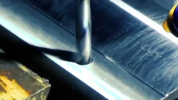
Los cortes de sierra y los orificios taladrados merecen una inspección temprana
Una hoja de sierra puede dejar un borde rugoso alrededor de la sección transversal del corte. Los dientes desafilados, una geometría de hoja inadecuada, una lubricación deficiente y ajustes de corte incorrectos pueden contribuir a ello. El aluminio adherido a un diente cambia su acción de corte1, por lo que la hoja comienza a empujar o desgarrar el material en lugar de separarlo limpiamente.
El taladrado a menudo deja su rebaba más visible en el momento de la perforación. El material restante se vuelve delgado a medida que el taladro se acerca al lado opuesto. La fuerza de corte puede empujar ese material hacia afuera antes de que se separe el borde2.
| Operación | Ubicación común de la rebaba | Primeros puntos a inspeccionar |
|---|---|---|
| Aserrado | Extremos cortados y paredes de secciones delgadas | Estado de los dientes, selección de la hoja, lubricación y avance |
| Perforación | Salida de orificio y aberturas en paredes delgadas | Afilado de la broca, avance de ruptura y soporte de la pieza de trabajo |
| Tapping | Entradas y salidas de roscas | Estado del macho, lubricación y grosor de la pared |
| Fresado de ranuras | Extremos de ranuras y bordes superiores o inferiores | Estado de la fresa, dirección de corte y eliminación de virutas |
Las paredes delgadas y las ranuras profundas requieren mayor atención
El roscado puede elevar el material alrededor de la entrada de una rosca, especialmente en una pared delgada. El fresado de ranuras puede dejar pequeños labios a lo largo de los bordes o rebabas más grandes donde la fresa abandona el material.
La inspección debe incluir las superficies ocultas dentro del perfil. Las ranuras profundas pueden retener virutas sueltas junto a rebabas adheridas. Estos son problemas distintos: la limpieza elimina las virutas sueltas, pero una rebaba adherida requiere corte u otro método de desbarbado.
El registro del proceso debe identificar la operación y el borde afectado. Ese detalle hace que el siguiente ajuste sea más útil que una nota general indicando que la pieza necesita desbarbado.
¿En qué se diferencian los bordes de entrada y salida en la formación de rebabas?
Una entrada limpia puede ocultar una salida rugosa. Esa rebaba oculta puede interferir con el ensamblaje, por lo que ambos lados de cada característica mecanizada requieren atención.
Las rebabas de entrada suelen ser más pequeñas porque el material circundante soporta el borde cuando comienza el corte. Las rebabas de salida suelen ser más grandes porque el material restante pierde soporte y se dobla o desgarra a medida que la herramienta sale. Las paredes delgadas hacen que esta diferencia sea especialmente notable durante el taladrado y el fresado.
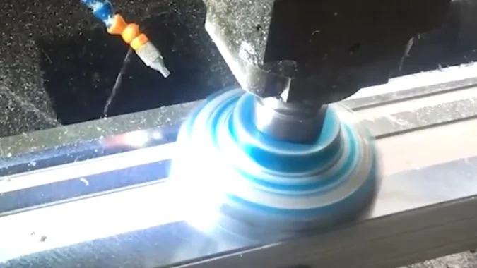
El soporte del borde cambia durante el corte
En la entrada, el filo de corte se encuentra con material que generalmente tiene soporte detrás. Una herramienta afilada puede comenzar a separar la viruta con menos doblado del borde de la pieza de trabajo.
En la salida, la sección restante se vuelve más fácil de deformar. El aluminio puede doblarse formando un labio antes de separarse debido a que el material es dúctil3. Una herramienta desgastada o una carga de corte pesada pueden aumentar esa deformación.
Este patrón es común, pero no es una regla absoluta. El grosor local de la pared, la dirección del corte y la geometría de la herramienta pueden cambiar qué borde presenta la rebaba más grande.
| Estado del borde | Comportamiento típico | Respuesta práctica |
|---|---|---|
| Entrada soportada | El borde generalmente resiste mejor la flexión | Mantenga una herramienta afilada y una entrada estable |
| Salida sin soporte | El material restante puede doblarse hacia afuera | Mejore el soporte y revise el movimiento de salida |
| Perforación de pared delgada | La pared puede desviarse antes de la separación | Check local rigidity and breakthrough feed |
| Exit inside a groove | The burr can remain difficult to reach | Plan inspection and deburring access early |
Tool paths should account for the final edge
Process planning should place critical exits near supported sections where the profile geometry allows. A controlled feed reduction near breakthrough can help when cutting force is pushing a thin edge outward4. The reduction still needs to preserve a clean cutting action.
Lubrication also matters because aluminum buildup changes the effective cutting edge5. A suitable tool geometry and reliable fluid delivery help maintain a cleaner cut.
Any remaining edge break should follow the drawing. A small chamfer can remove a burr, but its size must suit the required fit and edge condition.
¿Cómo deben revisarse los avances y velocidades cuando aumentan las rebabas?
Burr growth can turn a stable job into repeated rework. Tool checks and controlled parameter trials help identify the cause before more parts need cleanup.
A feed reduction is worth testing when excessive cutting force causes burrs, but tool wear and lubrication should be checked first. Cutting speed then needs review against heat, adhesion, and tool condition. Lower settings are useful only when they improve cutting instead of increasing rubbing.
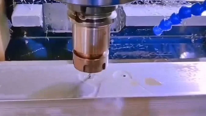
Tool condition comes before parameter changes
A sudden increase in burrs can indicate a dull edge, chipped tooth, or aluminum buildup. Lowering the feed cannot restore the geometry of a damaged tool. The operator should inspect the cutting edges and replace or resharpen worn tools as appropriate.
The coolant or lubrication system also needs checking at the cutting point. A running pump does not prove that fluid reaches the tool. Chips packed around the cutter can block delivery and damage the machined surface.
Feed and speed need separate, controlled trials
A lower feed can reduce force when the tool is pushing material outward6. The trial should use a small change and compare the same feature under otherwise similar conditions.
Cutting speed should then be reviewed against the observed problem. A reduction may help when excessive heat or rapid wear is present7. A blanket reduction is less useful when adhesion or rubbing is the main issue.
| Observation | First action | Parameter review |
|---|---|---|
| Burrs rise suddenly during a batch | Inspect wear and aluminum buildup | Restore tool condition before changing settings |
| A thin exit edge bends outward | Check support and cutting load | Test a controlled reduction near exit |
| Heat and tool wear rise together | Check lubrication and engagement | Review whether cutting speed is excessive |
| The surface looks smeared | Inspect adhesion and cutting geometry | Check whether the tool is rubbing |
| Chips collect in the slot | Restore chip removal | Review cut depth, width, and feed together |
The feed setting must suit the tool, spindle speed, and amount of material engaged. A finishing cut still needs to form a chip. An extremely low feed or shallow engagement can make the edge rub instead8.
The operator should record each change and inspect burr size, surface finish, and dimensions. A setting is useful only when it improves the part consistently.
¿Cuándo puede una pasada de acabado reducir las rebabas en ranuras fresadas?
A rough slot edge can survive an extra pass. Finishing helps when the tool removes a controlled allowance with stable support and a suitable cutting direction.
A finishing pass can reduce slot burrs when roughing leaves a small, consistent allowance and a sharp cutter removes it under stable conditions. Climb milling is often suitable for supported slot walls. Remaining top or bottom edge burrs may still need a separate chamfering or deburring operation.
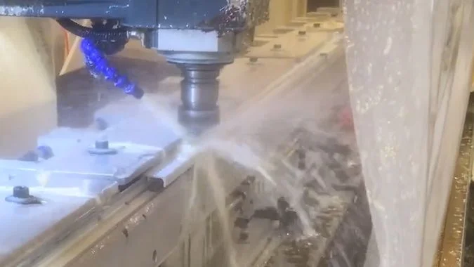
A finishing pass needs material to cut
The roughing path should leave a controlled allowance on the surfaces that need finishing. The finishing cutter can then remove that material with a lighter, more consistent load.
An extra pass over an already finished surface may not remove an attached edge burr. The cutter may miss its root or simply bend the lip. The finishing path needs to engage the affected area without taking the slot outside its dimensional limits.
| Slot condition | Likely value of a finishing pass | Process requirement |
|---|---|---|
| Rough walls with a consistent allowance | The pass can improve the wall and reduce edge tearing | Sharp cutter and controlled engagement |
| Burrs near the tool exit | A revised finishing path can reduce their formation | Supported exit and suitable feed |
| Burrs along a top or bottom edge | Wall finishing alone may leave them attached | Separate edge treatment where required |
| Flexible walls or packed chips | Another pass can repeat the defect | Better support and chip removal first |
Climb milling can improve the finishing cut
In peripheral climb milling, chip thickness starts larger and decreases toward the end of engagement9. This cutting action can help produce cleaner edges on aluminum10.
The machine, fixture, and profile must remain stable under the cutting force. A finishing path should account for thin walls, internal corners, and changes in engagement. Climb milling deserves consideration during both roughing and finishing when the setup supports it.
Separate finishing movements along the slot walls give the programmer more control over cutting direction and the final exit. Chips should clear the slot before they can be cut again or scratch the finished surface.
Remaining burrs need a defined removal step
A chamfering tool can remove small remaining burrs when the drawing allows an edge break11. The operation should follow the final cut that creates the burr.
Other mechanical deburring methods may suit particular part sizes and production volumes. Deep grooves need inspection after cleanup because detached burrs and chips can remain trapped inside the profile.
Conclusión
Sharp tools, balanced cutting settings, supported exits, and controlled finishing passes reduce aluminum profile burrs. Planned deburring and thorough cleaning address what remains.
-
"Effect of Built-Up Edge Formation during Stable State of Wear …", https://pmc.ncbi.nlm.nih.gov/articles/PMC5706177/. Material adhesion to cutting edges, known as built-up edge (BUE) formation, alters effective rake angle and increases cutting forces in aluminum machining, particularly at intermediate cutting speeds where adhesion is most pronounced. Evidence role: mechanism; source type: research. Supports: how material adhesion to cutting edges changes effective tool geometry and cutting mechanics. Scope note: Research typically addresses general BUE mechanisms rather than tooth-specific behavior in sawing operations ↩
-
"Experimental Study of Thrust Force and Torque for Drilling …", https://pubmed.ncbi.nlm.nih.gov/30627838/. During drill breakthrough, thrust force acting on the remaining thin material causes plastic deformation and bending before fracture, with burr size correlating to the ratio of thrust force to remaining material thickness. Evidence role: mechanism; source type: research. Supports: the relationship between drilling thrust force and material deformation at breakthrough. ↩
-
"Tool wear and burr formation during drilling of aluminum …", https://www.sciencedirect.com/science/article/pii/S2214785322001389. Materials with higher ductility, including aluminum alloys, exhibit greater plastic deformation before fracture during cutting, resulting in larger burrs through bending and tearing mechanisms rather than clean shearing. Evidence role: mechanism; source type: research. Supports: how ductility influences burr formation through plastic deformation before fracture. Scope note: Burr size depends on multiple factors beyond ductility, including cutting conditions and tool geometry ↩
-
"Figure 6 – from Burr formation minimization in drilling", https://www.academia.edu/figures/17127970/figure-7-height-of-burr-vs-speed-feed-rate-and-point-angle. Experimental studies demonstrate that reducing feed rate during the final portion of drilling operations decreases thrust force and exit burr height, though the optimal reduction timing and magnitude depend on material thickness and drill diameter. Evidence role: general_support; source type: research. Supports: the effectiveness of feed rate reduction strategies for exit burr control. ↩
-
"Effect of Cutting Fluid on Milled Surface Quality and Tool Life …", https://pmc.ncbi.nlm.nih.gov/articles/PMC10056421/. Effective lubrication reduces aluminum adhesion to cutting tools by lowering interface temperature and providing a boundary layer that inhibits metal-to-metal contact, thereby minimizing built-up edge formation. Evidence role: mechanism; source type: research. Supports: how lubrication reduces aluminum adhesion to cutting tools. Scope note: Effectiveness varies with lubricant chemistry, delivery method, and cutting speed range ↩
-
"Velocidades y avances", https://en.wikipedia.org/wiki/Speeds_and_feeds. Cutting forces increase approximately linearly with feed rate in most machining operations, as feed directly determines uncut chip thickness and therefore the material volume resisting deformation. Evidence role: mechanism; source type: research. Supports: the relationship between feed rate and cutting forces. ↩
-
"Optimizing Cutting Parameters for Enhanced Control of … – PMC", https://pmc.ncbi.nlm.nih.gov/articles/PMC11901140/. Cutting temperature increases with cutting speed due to higher shear rates and reduced heat dissipation time, with tool wear rate typically following an exponential relationship to cutting speed in most tool-material combinations. Evidence role: mechanism; source type: research. Supports: how cutting speed affects heat generation and tool wear rates. Scope note: Optimal speed ranges vary significantly with tool material, workpiece alloy, and cooling method ↩
-
"Estimation of Minimum Uncut Chip Thickness during Precision …", https://pmc.ncbi.nlm.nih.gov/articles/PMC8745993/. When uncut chip thickness falls below a critical value (typically 20-40% of cutting edge radius), material deformation transitions from shearing to ploughing and rubbing, increasing specific cutting energy and surface damage without effective material removal. Evidence role: mechanism; source type: research. Supports: the minimum chip thickness phenomenon and its relationship to rubbing. ↩
-
"Influence of Machining Parameters on Cutting and Chip … – PMC", https://pmc.ncbi.nlm.nih.gov/articles/PMC9502497/. In climb (down) milling, the cutter tooth enters the workpiece at maximum chip thickness and exits at zero, producing a chip that decreases in thickness through the engagement arc, in contrast to conventional (up) milling where chip thickness increases from entry to exit. Evidence role: mechanism; source type: education. Supports: the chip thickness variation pattern in climb milling. ↩
-
"Climb Milling vs. Conventional Milling", https://www.youtube.com/watch?v=galm5_6SUcM. Climb milling generally produces better surface finish and reduced exit burrs in aluminum machining because the cutting action directs forces into the workpiece rather than lifting material, though this advantage requires adequate machine rigidity to prevent chatter. Evidence role: general_support; source type: research. Supports: the edge quality advantages of climb milling in aluminum. Scope note: Benefits depend on machine stiffness, fixturing, and workpiece geometry; unstable setups may perform better with conventional milling ↩
-
"Deburring tool for soft materials: effective alternative to filing?", https://www.facebook.com/groups/769782850345135/posts/1627978804525531/. Chamfering operations effectively remove small to medium burrs while creating a controlled edge break, with process capability depending on burr size relative to chamfer dimensions and consistency of burr location. Evidence role: general_support; source type: research. Supports: the effectiveness of chamfering as a deburring method. Scope note: Effectiveness decreases for large or irregular burrs that exceed the chamfer envelope or vary in position ↩

Chris Lu
Aprovechando más de una década de experiencia práctica en la industria de la máquina herramienta, en particular con máquinas CNC, estoy aquí para ayudar. Si tiene alguna pregunta que le haya surgido a raíz de este artículo, si necesita orientación para seleccionar el equipo adecuado (CNC o convencional), si está explorando soluciones de máquinas personalizadas o si está listo para discutir una compra, no dude en CONTACTAR CONMIGO. Encontremos la máquina herramienta perfecta para sus necesidades.