

Come scegliere il diametro del filo di molibdeno per la propria macchina HS-WEDM o MS-WEDM?
Un filo di molibdeno spesso taglia più velocemente e lascia un solco più largo. Un filo sottile mantiene un angolo più vivo ma si rompe più facilmente. Il diametro deve essere scelto in base allo spessore del pezzo e alla precisione richiesta.
Il diametro del filo di molibdeno per macchine HS-WEDM o MS-WEDM viene scelto in base allo spessore del pezzo e alla precisione necessaria. Le dimensioni comuni sono 0,12–0,20 mm. Per un primo taglio si usa spesso 0,18 mm. Per un taglio di finitura si usa 0,15 mm o inferiore. Superare i 0,23 mm su una macchina a filo veloce causa accumuli.
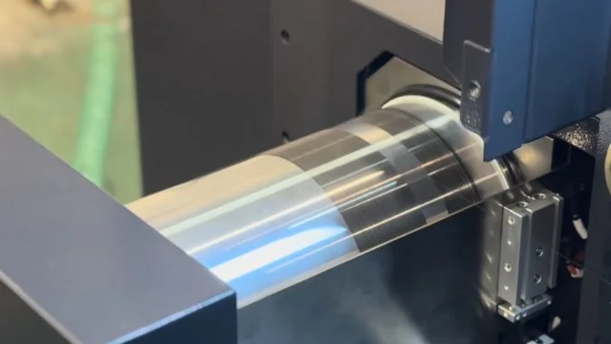
Un filo da 0,18 mm e uno da 0,12 mm non tagliano la stessa asola. Il filo più spesso crea un solco più ampio e procede più velocemente. Il filo più sottile lascia un raggio minore negli angoli interni. Lo spessore del pezzo e il disegno dell'angolo determinano quale diametro deve essere utilizzato sulla macchina.
Che ruolo ha il diametro del filo nella larghezza del solco, nell'angolo interno e nella velocità di taglio?
Un unico diametro non può soddisfare contemporaneamente le esigenze di solco, angolo e velocità. Il risultato sarà un'asola troppo larga, un angolo smussato o un taglio lento. I tre effetti devono essere considerati insieme.
Il diametro del filo determina la larghezza del solco, il raggio lasciato in un angolo interno e la velocità di taglio. Un filo più spesso allarga il solco e taglia più velocemente, ma lascia un arco d'angolo maggiore. Un filo più sottile restringe il solco e permette di avvicinarsi a un angolo più vivo.
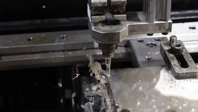
Larghezza del solco
La larghezza del solco corrisponde al diametro del filo di molibdeno più lo scarico di scarica su entrambi i lati1. Un filo più spesso crea un'asola più larga. Un filo più sottile crea un'asola più stretta. La compensazione del programma è pari al raggio del filo più lo scarico su un lato. Il filo si usura diventando più sottile durante il lavoro, quindi la larghezza del solco e la dimensione finale variano. Il diametro dovrebbe essere misurato secondo una pianificazione prestabilita e il valore di compensazione aggiornato di conseguenza.
Angolo interno
Un filo più spesso lascia un arco maggiore in un angolo interno, rendendo difficile ottenere un angolo vivo. Un filo più sottile lascia un arrotondamento minore, permettendo al percorso di avvicinarsi di più a un angolo netto. Gli stampi piccoli con angoli vivi e asole strette richiedono fili più sottili. L'elettroerosione a filo per stampi è una scelta di processo specifica. Il diametro continua a determinare quanto piccolo possa essere l'angolo residuo.
Velocità di taglio
Un filo più spesso può trasportare una maggiore corrente di scarica, rendendo il taglio più rapido. I pezzi spessi favoriscono questa velocità. Lo stesso filo spesso, tuttavia, riduce la qualità superficiale. Lo spessore del pezzo, il materiale e la precisione richiesta dal disegno devono essere valutati insieme prima di definire il diametro.
Diametri comuni per HS-WEDM e MS-WEDM
Le lavorazioni convenzionali con filo veloce e medio utilizzano diametri tra 0,12 e 0,20 mm. Per il primo taglio si usa spesso 0,18 mm. Per una passata di finitura si passa a 0,15 mm o meno. Un obiettivo di Ra 0,4 μm o migliore favorisce l'uso di 0,12–0,15 mm, mantenendo la tensione costante. Pezzi spessi e correnti elevate favoriscono 0,18 mm o più. HS-WEDM e MS-WEDM sono macchine diverse, ma la regola del diametro su entrambe dipende sempre dal pezzo.
| Effetto | Filo più spesso | Filo più sottile |
|---|---|---|
| Taglio (Kerf) | Più largo. Diametro più gioco su entrambi i lati | Più stretto |
| Angolo interno | Arco residuo più grande | Raggio più piccolo, più vicino a uno spigolo vivo |
| Velocità di taglio | Più veloce. Migliore su pezzi spessi | Più lento |
| Superficie | Solitamente peggiore | Migliore quando la tensione è mantenuta |
| Dimensione tipica | Primo taglio a 0,18 mm, o più spesso per materiale pesante | Passata di finitura a 0,15 mm, o 0,12–0,15 mm per una finitura fine |
Perché un filo di molibdeno più spesso conduce meglio la corrente su un blocco d'acciaio spesso?
Un blocco d'acciaio spesso richiede una corrente media maggiore. Un filo sottile si surriscalda e si spezza sotto tale carico. La sezione trasversale è ciò che stabilisce la corrente che il filo può trasportare.
Un filo di molibdeno più spesso trasporta meglio la corrente su un blocco d'acciaio spesso perché la sua sezione trasversale è maggiore. A circa 150 A/mm², un filo da 0,18 mm può sopportare circa 3,82 A. Un filo da 0,12 mm è vicino a 1,74 A.
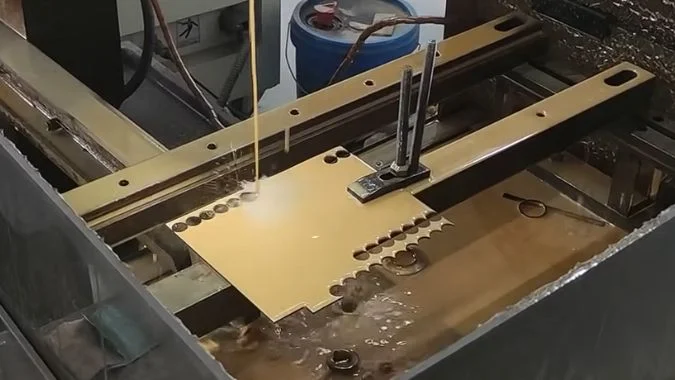
Perché la sezione stabilisce la corrente
L'elettroerosione a filo fonde il metallo con una scarica a impulsi. Il filo di molibdeno è l'elettrodo che trasporta tale corrente. La capacità di corrente segue la sezione trasversale. Un filo più spesso può trasportare più corrente prima di rompersi. Un riferimento industriale pone il limite di taglio vicino a 150 A/mm². A quella densità, la resistenza alla trazione scende a circa un terzo o un quarto della resistenza originale2. Su questa base, un filo da 0,12 mm è vicino a 1,74 A. Un filo da 0,18 mm è vicino a 3,82 A. Il divario tra questi due limiti è ampio.
Cosa richiede un blocco d'acciaio spesso
Un blocco spesso ha un lungo percorso di scarica. I trucioli sono difficili da rimuovere. Un'erosione efficace richiede una corrente media più elevata. Il blocco trasforma anche più di quell'energia in calore. Il filo spesso assorbe la corrente. Ha una resistenza inferiore e genera meno calore nel filo stesso. Un punto caldo locale ha quindi meno probabilità di strappare il filo. Nell'acciaio spesso, il filo da 0,18 mm è molto più stabile rispetto al filo da 0,12 mm.
Dove uno spessore maggiore smette di essere utile
Il taglio più largo e un profilo leggermente peggiore sono il costo di quella corrente. Più spesso non è sempre meglio. Sopra 0,23 mm su una macchina a filo rapido, il filo può accumularsi e deflettere. Tale dimensione fa più male che bene. Per materiale spesso e corrente elevata occorrono 0,18 mm o più. Per piccole parti di precisione che richiedono finitura occorrono 0,12–0,15 mm.
| Filo | Corrente approssimativa vicina a 150 A/mm² | Adattamento su un blocco di acciaio spesso |
|---|---|---|
| 0,12 mm | Circa 1,74 A | Si surriscalda e si rompe sotto la corrente necessaria per un blocco spesso |
| 0,18 mm | Circa 3,82 A | More stable. Lower resistance and less heat in the wire |
| Above 0.23 mm on fast-wire | Higher section, but poor wire behavior | Pile-up and deflection. Not a gain |
| 0.12–0.15 mm on small precise parts | Lower current | Finish and corner, not thick-block speed |
Cosa succede alla finitura se si utilizza lo stesso diametro sia per il taglio di sgrossatura che per quello di finitura?
One wire that roughs and then skims copies the roughing damage onto the face. Roughness stays high, and streaks appear. The wire must be checked or changed.
Forcing one molybdenum wire through both rough and skim cuts leaves a worn, pitted wire on the finish pass. Ra often stays at 1.2–1.4 μm and will not settle below 1.0 μm. Wear over 0.01 mm means the wire should be replaced.
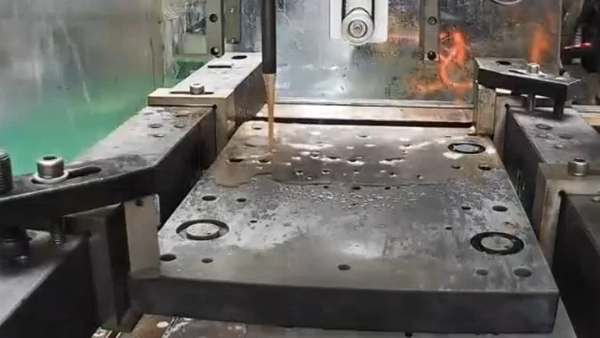
What the face shows
The same wire for roughing and skimming copies wire damage onto the part. Roughness will not settle below Ra 1.0 μm. It often sits at Ra 1.2–1.4 μm, or worse. Uneven wear or local pits leave regular light and dark streaks, like wire-jump marks. A thinning wire makes the discharge gap unstable. A short pulse interval then leaves irregular pits. Dirty fluid adds a yellow cast or carbon on the face.
Why the roughing wire cannot skim
High current in the rough cut thins the wire and puts micro-pits in its surface. Neither the new diameter nor that surface is stable enough for a skim. Wear over 0.01 mm is the usual change point. Past that loss, finish quality cannot be held. Roughing and skimming also want different tension. One wire moving between those states changes kerf width and surface texture. Deep discharge pits and the altered layer from the first cut may also be too deep for later passes to clear. The finish then has a ceiling.
What to change before the skim
Separate wires when the machine allows it. About 0.18 mm for roughing. 0.12–0.15 mm for skimming. Current capacity and kerf width then match each pass. If one wire must stay, measure it after roughing. Replace it when wear exceeds 0.01 mm. For the skim, hold pulse width within 4 μs3, slow the wire speed, and set tension at 12–14 N4. A finish below Ra 0.8 μm is basically out of reach on that same molybdenum wire5. Separate wires, or a slow-wire process, are the remaining paths.
| Check | Same wire through rough and skim | Separate wires |
|---|---|---|
| Wire after roughing | Thinned and micro-pitted | Roughing wire stops at the rough cut |
| Typical Ra | Often 1.2–1.4 μm. Hard to hold below 1.0 μm | Skim wire is 0.12–0.15 mm and still round |
| Wear limit | Over 0.01 mm: change before the skim | Not shared, so roughing wear does not enter the skim |
| Below Ra 0.8 μm | Basically not reachable | Separate wires, or slow-wire EDM |
| Skim settings if the wire must stay | Pulse width within 4 μs, slower wire, tension 12–14 N | Not required for a fresh skim wire |
Perché un filo sottile si rompe più spesso durante tagli interrotti o in presenza di un lavaggio insufficiente?
Interrupted cuts and weak flushing pile heat and debris on a thin wire. The wire then burns or snaps. Flush pressure and the broken end show the cause.
A thin molybdenum wire breaks more often on interrupted cuts with poor flushing because heat and debris stay in a narrow kerf. The wire has less section, higher resistance, and less cooling. Breakage rises sharply when pump pressure is below 0.5 bar.
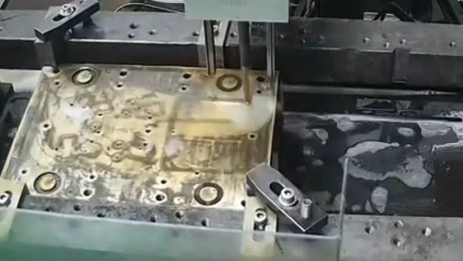
Taglio interrotto
An interrupted path makes the discharge jump between short circuit and open circuit. The wire takes repeated current shocks. An unstable discharge can also park an arc on one short length of wire. That spot overheats and breaks.
Poor flushing
Low flow, or a blocked path, keeps working fluid out of the kerf. Eroded debris stays in the slot. Short circuits form. Heat is not carried off. Wire temperature rises until the wire passes its limit. Breakage rises sharply when circulation pump pressure is below 0.5 bar. Fluid concentration should stay inside the maker’s recommended range.
Why thin wire fails first
A thinner wire has less cross-section. Resistance is higher. Current capacity is lower. Cooling is worse. The kerf is also narrower, so chips leave more slowly. The same heat and the same debris break a thin wire sooner than a thick wire.
What the broken end shows
A molten ball on the broken end points to overheating. Discharge settings and fluid supply are the first check. A flat end with no sign of melting points to a mechanical pull. Tension, guide pulleys, and electrical contact blocks are the first check.
| Condizione | What it does to a thin wire | First check |
|---|---|---|
| Interrupted cut | Repeated shorts, opens, and a parked arc | Discharge stability on the break length |
| Flush below 0.5 bar | Heat and debris stay in the kerf | Pump pressure and flow into the slot |
| Fluid off the maker’s range | Poor cooling and poor chip removal | Concentration |
| Molten ball on the broken end | High-temperature break | Discharge parameters and fluid supply |
| Flat broken end, no melt | Mechanical pull | Tension, guide pulleys, contact blocks |
Conclusione
Thick steel takes 0.18 mm or thicker. Corners and skim cuts take 0.12–0.15 mm. A worn roughing wire should not stay on for the finish.
-
"Prediction of Kerf Width and Surface Roughness of Al6351 …", https://pmc.ncbi.nlm.nih.gov/articles/PMC8839751/. In wire electrical discharge machining, the kerf width is determined by the wire diameter plus the spark gap that forms on each side of the wire during the discharge process, with the gap typically ranging from 0.01 to 0.05 mm depending on machining parameters. Evidence role: mechanism; source type: encyclopedia. Supports: the geometric relationship between wire diameter, spark gap, and resulting kerf width in EDM. ↩
-
"Study of the Structure and Mechanical Properties after … – PMC", https://pmc.ncbi.nlm.nih.gov/articles/PMC8878319/. Research on molybdenum wire behavior under thermal and electrical loading demonstrates that elevated temperatures from current flow can reduce tensile strength substantially, with reductions of 50–75% observed at temperatures approaching the wire’s operational limits in EDM. Evidence role: mechanism; source type: paper. Supports: the effect of thermal loading on molybdenum wire mechanical properties. Scope note: The degree of strength reduction depends on temperature distribution, exposure time, and wire microstructure, making the relationship context-dependent rather than a fixed ratio. ↩
-
"Optimization of WEDM Parameters While Machining … – PMC", https://pmc.ncbi.nlm.nih.gov/articles/PMC9821652/. Research on wire EDM finishing parameters indicates that shorter pulse durations, typically in the range of 1–5 μs, produce finer surface finishes by reducing the energy per discharge and the resulting crater size on the workpiece surface. Evidence role: general_support; source type: paper. Supports: the relationship between pulse duration and surface finish in wire EDM. Scope note: Optimal pulse width depends on material properties, wire diameter, and desired finish, so the cited value represents a typical range rather than a universal setting. ↩
-
"Optimization of WEDM Parameters While Machining … – PMC", https://pmc.ncbi.nlm.nih.gov/articles/PMC9821652/. Studies on wire EDM process parameters indicate that wire tension for finishing operations typically ranges from 10–20 N depending on wire diameter and material, with higher tension improving dimensional accuracy but requiring careful control to avoid wire breakage. Evidence role: general_support; source type: research. Supports: typical wire tension ranges used in wire EDM finishing operations. Scope note: Optimal tension varies with wire diameter, material, and machine design, so the cited range represents common practice for typical wire sizes rather than a universal specification. ↩
-
"Experimental Investigation of Surface Roughness and … – PMC", https://pmc.ncbi.nlm.nih.gov/articles/PMC9920754/. Experimental investigations of wire EDM finishing demonstrate that achieving surface roughness below Ra 0.8 μm typically requires fresh wire and optimized finishing parameters, as wire degradation from prior cutting operations introduces surface irregularities that limit finish quality. Evidence role: general_support; source type: paper. Supports: surface finish limitations when using worn wire in wire EDM. Scope note: The achievable finish depends on multiple factors including material, wire type, and machine capability, so the cited threshold represents typical practice rather than a fundamental limit. ↩

Chris Lu
Avvalendomi di oltre un decennio di esperienza pratica nel settore delle macchine utensili, in particolare con le macchine CNC, sono qui per aiutarvi. Se avete domande suscitate da questo post, se avete bisogno di una guida per la scelta dell'attrezzatura giusta (CNC o convenzionale), se state esplorando soluzioni di macchine personalizzate o se siete pronti a discutere un acquisto, non esitate a CONTATTARMI. Troviamo la macchina utensile perfetta per le vostre esigenze.