

How Can You Reduce Burrs When Machining Aluminum Profiles?
Burrs on aluminum profiles add manual work and can disturb assembly. A cleaner process starts with sharp tools, controlled cutting conditions, and better edge support.
Burrs on aluminum profiles can be reduced with sharp tools, suitable cutting geometry, balanced feeds and speeds, effective lubrication, and stable tool paths. Supported exit edges and controlled finishing passes help limit tearing. Chamfering or another suitable deburring process removes remaining burrs.
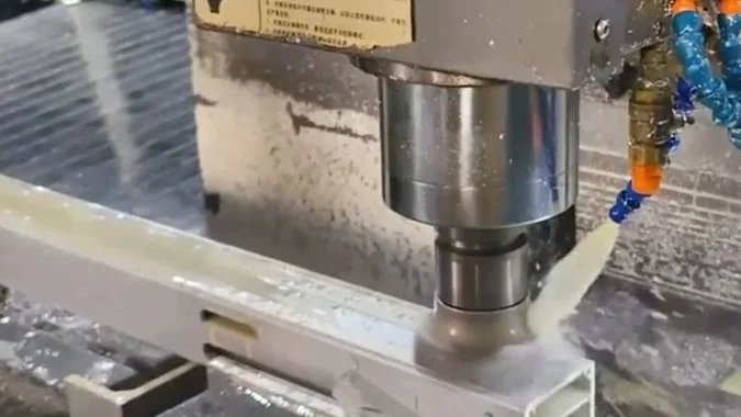
A profile can leave the machine with clean faces and rough edges around individual features. Those edges reveal where the cutting process needs attention. A saw cut, a drilled hole, and a milled slot create different conditions. The first useful step is to identify which operation leaves the burr and where it appears.
What Profile Machining Operations Are Most Likely to Leave Burrs?
Some operations leave more edge cleanup than others. Unplanned deburring increases handling time, so the inspection should start with saw cuts, drilled holes, threads, and slots.
Sawing and drilling are common sources of burrs on aluminum profiles, especially at unsupported exit edges. Tapping and slot milling also leave burrs around thin walls, thread openings, and slot edges. Tool condition, lubrication, and local support determine which operation creates the greatest problem.
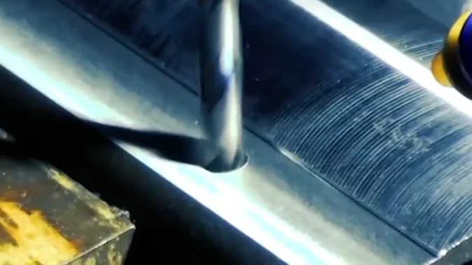
Saw cuts and drilled holes deserve early checks
A saw blade can leave a rough lip around the cut cross-section. Dull teeth, unsuitable blade geometry, poor lubrication, and incorrect cutting settings can all contribute. Aluminum stuck to a tooth changes its cutting action1, so the blade starts pushing or tearing material instead of separating it cleanly.
Drilling often leaves its most visible burr at breakthrough. The remaining material becomes thin as the drill approaches the far side. Cutting force can push that material outward before the edge separates2.
| Operation | Common burr location | First points to inspect |
|---|---|---|
| Sawing | Cut ends and thin section walls | Tooth condition, blade selection, lubrication, and feed |
| Drilling | Hole exit and thin wall openings | Drill sharpness, breakthrough feed, and workpiece support |
| Tapping | Thread entrances and exits | Tap condition, lubrication, and wall thickness |
| Slot milling | Slot ends and upper or lower edges | Cutter condition, cutting direction, and chip removal |
Thin walls and deep grooves need closer attention
Tapping can raise material around a thread opening, especially in a thin wall. Slot milling can leave small lips along the edges or larger burrs where the cutter leaves the material.
The inspection should include hidden surfaces inside the profile. Deep grooves can retain loose chips alongside attached burrs. These are different problems: cleaning removes loose chips, but an attached burr needs cutting or another deburring method.
The process record should identify the operation and the affected edge. That detail makes the next adjustment more useful than a general note that the part needs deburring.
How Do Entry and Exit Edges Differ in Burr Formation?
A clean entrance can hide a rough exit. That hidden burr can interfere with assembly, so both sides of each machined feature need attention.
Entry burrs are often smaller because surrounding material supports the edge as cutting begins. Exit burrs are often larger because the remaining material loses support and bends or tears as the tool leaves. Thin walls make this difference especially noticeable during drilling and milling.
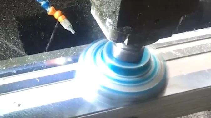
Edge support changes during the cut
At entry, the cutting edge meets material that usually has support behind it. A sharp tool can start separating the chip with less bending of the workpiece edge.
At exit, the remaining section becomes easier to deform. Aluminum can bend into a lip before it separates because the material is ductile3. A worn tool or heavy cutting load can increase that deformation.
This pattern is common, but it is not an absolute rule. Local wall thickness, cutting direction, and tool geometry can change which edge carries the largest burr.
| Edge condition | Typical behavior | Practical response |
|---|---|---|
| Supported entry | The edge usually resists bending better | Maintain a sharp tool and stable entry |
| Unsupported exit | The remaining material can fold outward | Improve support and review the exit movement |
| Thin wall breakthrough | The wall can deflect before separation | Check local rigidity and breakthrough feed |
| Exit inside a groove | The burr can remain difficult to reach | Plan inspection and deburring access early |
Tool paths should account for the final edge
Process planning should place critical exits near supported sections where the profile geometry allows. A controlled feed reduction near breakthrough can help when cutting force is pushing a thin edge outward4. The reduction still needs to preserve a clean cutting action.
Lubrication also matters because aluminum buildup changes the effective cutting edge5. A suitable tool geometry and reliable fluid delivery help maintain a cleaner cut.
Any remaining edge break should follow the drawing. A small chamfer can remove a burr, but its size must suit the required fit and edge condition.
How Should Feeds and Speeds Be Reviewed When Burrs Increase?
Burr growth can turn a stable job into repeated rework. Tool checks and controlled parameter trials help identify the cause before more parts need cleanup.
A feed reduction is worth testing when excessive cutting force causes burrs, but tool wear and lubrication should be checked first. Cutting speed then needs review against heat, adhesion, and tool condition. Lower settings are useful only when they improve cutting instead of increasing rubbing.
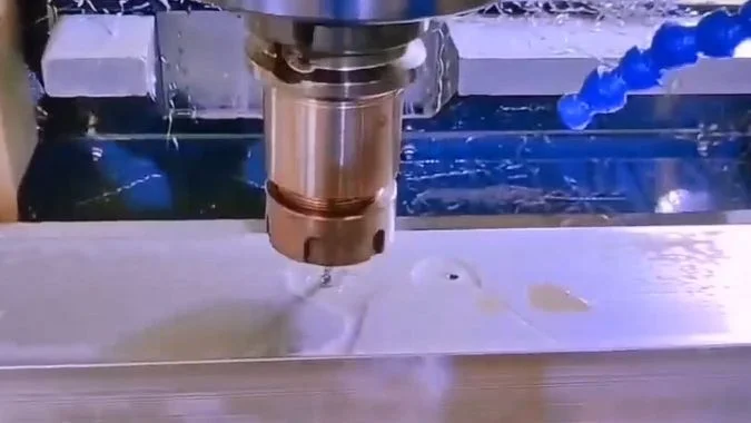
Tool condition comes before parameter changes
A sudden increase in burrs can indicate a dull edge, chipped tooth, or aluminum buildup. Lowering the feed cannot restore the geometry of a damaged tool. The operator should inspect the cutting edges and replace or resharpen worn tools as appropriate.
The coolant or lubrication system also needs checking at the cutting point. A running pump does not prove that fluid reaches the tool. Chips packed around the cutter can block delivery and damage the machined surface.
Feed and speed need separate, controlled trials
A lower feed can reduce force when the tool is pushing material outward6. The trial should use a small change and compare the same feature under otherwise similar conditions.
Cutting speed should then be reviewed against the observed problem. A reduction may help when excessive heat or rapid wear is present7. A blanket reduction is less useful when adhesion or rubbing is the main issue.
| Observation | First action | Parameter review |
|---|---|---|
| Burrs rise suddenly during a batch | Inspect wear and aluminum buildup | Restore tool condition before changing settings |
| A thin exit edge bends outward | Check support and cutting load | Test a controlled reduction near exit |
| Heat and tool wear rise together | Check lubrication and engagement | Review whether cutting speed is excessive |
| The surface looks smeared | Inspect adhesion and cutting geometry | Check whether the tool is rubbing |
| Chips collect in the slot | Restore chip removal | Review cut depth, width, and feed together |
The feed setting must suit the tool, spindle speed, and amount of material engaged. A finishing cut still needs to form a chip. An extremely low feed or shallow engagement can make the edge rub instead8.
The operator should record each change and inspect burr size, surface finish, and dimensions. A setting is useful only when it improves the part consistently.
When Can a Finishing Pass Reduce Burrs on Milled Slots?
A rough slot edge can survive an extra pass. Finishing helps when the tool removes a controlled allowance with stable support and a suitable cutting direction.
A finishing pass can reduce slot burrs when roughing leaves a small, consistent allowance and a sharp cutter removes it under stable conditions. Climb milling is often suitable for supported slot walls. Remaining top or bottom edge burrs may still need a separate chamfering or deburring operation.
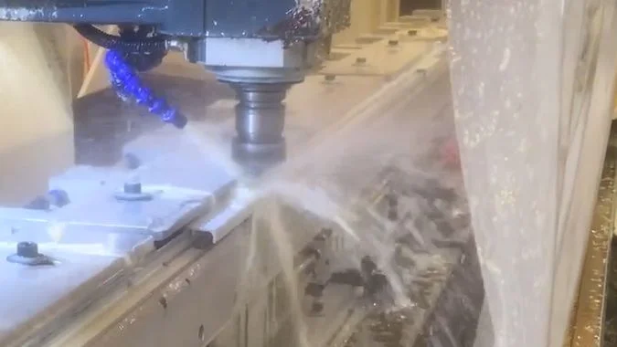
A finishing pass needs material to cut
The roughing path should leave a controlled allowance on the surfaces that need finishing. The finishing cutter can then remove that material with a lighter, more consistent load.
An extra pass over an already finished surface may not remove an attached edge burr. The cutter may miss its root or simply bend the lip. The finishing path needs to engage the affected area without taking the slot outside its dimensional limits.
| Slot condition | Likely value of a finishing pass | Process requirement |
|---|---|---|
| Rough walls with a consistent allowance | The pass can improve the wall and reduce edge tearing | Sharp cutter and controlled engagement |
| Burrs near the tool exit | A revised finishing path can reduce their formation | Supported exit and suitable feed |
| Burrs along a top or bottom edge | Wall finishing alone may leave them attached | Separate edge treatment where required |
| Flexible walls or packed chips | Another pass can repeat the defect | Better support and chip removal first |
Climb milling can improve the finishing cut
In peripheral climb milling, chip thickness starts larger and decreases toward the end of engagement9. This cutting action can help produce cleaner edges on aluminum10.
The machine, fixture, and profile must remain stable under the cutting force. A finishing path should account for thin walls, internal corners, and changes in engagement. Climb milling deserves consideration during both roughing and finishing when the setup supports it.
Separate finishing movements along the slot walls give the programmer more control over cutting direction and the final exit. Chips should clear the slot before they can be cut again or scratch the finished surface.
Remaining burrs need a defined removal step
A chamfering tool can remove small remaining burrs when the drawing allows an edge break11. The operation should follow the final cut that creates the burr.
Other mechanical deburring methods may suit particular part sizes and production volumes. Deep grooves need inspection after cleanup because detached burrs and chips can remain trapped inside the profile.
Conclusion
Sharp tools, balanced cutting settings, supported exits, and controlled finishing passes reduce aluminum profile burrs. Planned deburring and thorough cleaning address what remains.
-
"Effect of Built-Up Edge Formation during Stable State of Wear …", https://pmc.ncbi.nlm.nih.gov/articles/PMC5706177/. Material adhesion to cutting edges, known as built-up edge (BUE) formation, alters effective rake angle and increases cutting forces in aluminum machining, particularly at intermediate cutting speeds where adhesion is most pronounced. Evidence role: mechanism; source type: research. Supports: how material adhesion to cutting edges changes effective tool geometry and cutting mechanics. Scope note: Research typically addresses general BUE mechanisms rather than tooth-specific behavior in sawing operations ↩
-
"Experimental Study of Thrust Force and Torque for Drilling …", https://pubmed.ncbi.nlm.nih.gov/30627838/. During drill breakthrough, thrust force acting on the remaining thin material causes plastic deformation and bending before fracture, with burr size correlating to the ratio of thrust force to remaining material thickness. Evidence role: mechanism; source type: research. Supports: the relationship between drilling thrust force and material deformation at breakthrough. ↩
-
"Tool wear and burr formation during drilling of aluminum …", https://www.sciencedirect.com/science/article/pii/S2214785322001389. Materials with higher ductility, including aluminum alloys, exhibit greater plastic deformation before fracture during cutting, resulting in larger burrs through bending and tearing mechanisms rather than clean shearing. Evidence role: mechanism; source type: research. Supports: how ductility influences burr formation through plastic deformation before fracture. Scope note: Burr size depends on multiple factors beyond ductility, including cutting conditions and tool geometry ↩
-
"Figure 6 – from Burr formation minimization in drilling", https://www.academia.edu/figures/17127970/figure-7-height-of-burr-vs-speed-feed-rate-and-point-angle. Experimental studies demonstrate that reducing feed rate during the final portion of drilling operations decreases thrust force and exit burr height, though the optimal reduction timing and magnitude depend on material thickness and drill diameter. Evidence role: general_support; source type: research. Supports: the effectiveness of feed rate reduction strategies for exit burr control. ↩
-
"Effect of Cutting Fluid on Milled Surface Quality and Tool Life …", https://pmc.ncbi.nlm.nih.gov/articles/PMC10056421/. Effective lubrication reduces aluminum adhesion to cutting tools by lowering interface temperature and providing a boundary layer that inhibits metal-to-metal contact, thereby minimizing built-up edge formation. Evidence role: mechanism; source type: research. Supports: how lubrication reduces aluminum adhesion to cutting tools. Scope note: Effectiveness varies with lubricant chemistry, delivery method, and cutting speed range ↩
-
"Speeds and feeds", https://en.wikipedia.org/wiki/Speeds_and_feeds. Cutting forces increase approximately linearly with feed rate in most machining operations, as feed directly determines uncut chip thickness and therefore the material volume resisting deformation. Evidence role: mechanism; source type: research. Supports: the relationship between feed rate and cutting forces. ↩
-
"Optimizing Cutting Parameters for Enhanced Control of … – PMC", https://pmc.ncbi.nlm.nih.gov/articles/PMC11901140/. Cutting temperature increases with cutting speed due to higher shear rates and reduced heat dissipation time, with tool wear rate typically following an exponential relationship to cutting speed in most tool-material combinations. Evidence role: mechanism; source type: research. Supports: how cutting speed affects heat generation and tool wear rates. Scope note: Optimal speed ranges vary significantly with tool material, workpiece alloy, and cooling method ↩
-
"Estimation of Minimum Uncut Chip Thickness during Precision …", https://pmc.ncbi.nlm.nih.gov/articles/PMC8745993/. When uncut chip thickness falls below a critical value (typically 20-40% of cutting edge radius), material deformation transitions from shearing to ploughing and rubbing, increasing specific cutting energy and surface damage without effective material removal. Evidence role: mechanism; source type: research. Supports: the minimum chip thickness phenomenon and its relationship to rubbing. ↩
-
"Influence of Machining Parameters on Cutting and Chip … – PMC", https://pmc.ncbi.nlm.nih.gov/articles/PMC9502497/. In climb (down) milling, the cutter tooth enters the workpiece at maximum chip thickness and exits at zero, producing a chip that decreases in thickness through the engagement arc, in contrast to conventional (up) milling where chip thickness increases from entry to exit. Evidence role: mechanism; source type: education. Supports: the chip thickness variation pattern in climb milling. ↩
-
"Climb Milling vs. Conventional Milling", https://www.youtube.com/watch?v=galm5_6SUcM. Climb milling generally produces better surface finish and reduced exit burrs in aluminum machining because the cutting action directs forces into the workpiece rather than lifting material, though this advantage requires adequate machine rigidity to prevent chatter. Evidence role: general_support; source type: research. Supports: the edge quality advantages of climb milling in aluminum. Scope note: Benefits depend on machine stiffness, fixturing, and workpiece geometry; unstable setups may perform better with conventional milling ↩
-
"Deburring tool for soft materials: effective alternative to filing?", https://www.facebook.com/groups/769782850345135/posts/1627978804525531/. Chamfering operations effectively remove small to medium burrs while creating a controlled edge break, with process capability depending on burr size relative to chamfer dimensions and consistency of burr location. Evidence role: general_support; source type: research. Supports: the effectiveness of chamfering as a deburring method. Scope note: Effectiveness decreases for large or irregular burrs that exceed the chamfer envelope or vary in position ↩

Chris Lu
Leveraging over a decade of hands-on experience in the machine tool industry, particularly with CNC machines, I'm here to help. Whether you have questions sparked by this post, need guidance on selecting the right equipment (CNC or conventional), are exploring custom machine solutions, or are ready to discuss a purchase, don't hesitate to CONTACT Me. Let's find the perfect machine tool for your needs.