

Wanneer is een profielbewerkingscentrum beter dan een standaard VMC voor lange aluminium onderdelen?
Wanneer is een profielbewerkingscentrum beter dan een standaard VMC voor lange aluminium onderdelen?
Long aluminum parts can exceed a VMC’s practical working area1. Extra setups add handling and alignment work2, so machine selection should begin with the complete process.
A profile machining center is better when its usable machining length, profile supports, and multi-face access remove repeated setups that a standard VMC would require. The advantage depends on the actual part, fixture, tolerances, and cutting load. Both machines should be compared against the same production requirements.
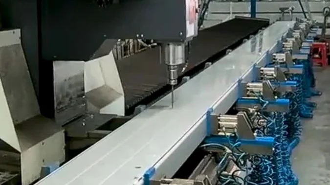
A long extrusion can contain a row of holes, a continuous slot, and features on opposite faces. Each feature has a location tied to the part datum. The machine comparison starts with a drawing laid over the proposed fixture. That layout shows which features remain reachable and which operations would force a change of setup.
Welke vereisten voor de bewerking van lange onderdelen kunnen een standaard VMC onpraktisch maken?
A part may fit on a VMC table and still be difficult to machine. The required tool paths and support positions reveal the practical limits.
A standard VMC becomes impractical when critical features exceed its reachable cutting area, repeated setups cannot meet alignment requirements, or the long profile cannot be supported securely. A profile machining center offers an advantage when its bed, clamps, and axis configuration cover those requirements in one setup.
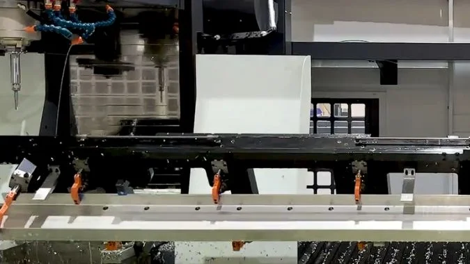
The feature span determines the required reach
Part length and required machining length can differ. A long extrusion with all machining near one end may remain practical on a VMC with suitable support and clearance. A continuous slot or hole pattern spanning most of the extrusion creates a different requirement3. The cutter must reach the full feature range in a controlled setup.
The comparison should include the table, enclosure, loading route, and space for supported overhang. The profile must remain clear of the machine structure throughout movement.
| Production requirement | Practical limit to check on the VMC | Potential profile machining center advantage |
|---|---|---|
| A hole pattern spans the part | The tool cannot reach both ends in one setup | A longer usable machining range covers the pattern |
| A continuous slot crosses setup boundaries | Separate cuts require careful alignment | One tool path avoids a joint between setups |
| Top and side features share a datum | Turning the part requires another alignment | The selected head or indexing system provides access |
| A hollow profile bends under cutting load | Support positions are limited | Distributed supports hold the profile near the cut |
Face access and handling affect batch production
Top and side features require a confirmed access method. A swivelling spindle, angular head, or indexing fixture can reduce turning and reclamping. The selected configuration must reach the specified faces with the actual tools.
A stationary profile and travelling machining unit can simplify support along a long bed4. The supports still need to resist cutting forces without crushing hollow walls.
Batch comparisons should count loading, alignment, clamp movement, machining, and unloading. A VMC remains suitable when the features fit, the fixture is stable, and the complete cycle meets production needs.
Hoe kan herhaaldelijk verplaatsen de gatafstand en de uitlijning van kenmerken beïnvloeden?
Each new setup can change the part’s location and supported shape. Assembly errors become harder to diagnose, so the comparison should track features across setup boundaries.
Repeated repositioning can shift or rotate the part datum and change its supported shape. Hole spacing across separate setups and alignment between slots or faces can then drift. Features produced within one setup may remain accurate relative to each other, even when the whole group is misplaced.
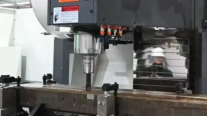
A shifted datum affects relationships between setups
A group of holes can have correct internal spacing and still sit in the wrong position relative to the far end of the profile. This happens when the second setup establishes a different datum.
Angular alignment also matters. A small rotation during reclamping creates a larger lateral difference farther from the reference point5. A long slot can then show a step at the join between two machining positions.
| Change during repositioning | Possible effect on the part | Useful inspection |
|---|---|---|
| The longitudinal stop position changes | Hole groups move closer together or farther apart | Distance between holes from different setups |
| The profile rotates slightly | Slots or hole rows lose alignment | Alignment over the full specified span |
| Clamp pressure changes | Thin walls move during cutting | Dimensions in the required inspection condition |
| Support locations change | The profile bends differently | Feature position and shape after release |
Machine repeatability and setup repeatability need separate checks
Axis repeatability describes repeated machine positioning under defined test conditions6. It does not include every change caused by moving the workpiece, cleaning a stop, or tightening a clamp.
Repositioning errors can combine, but they do not always grow by the same amount or in the same direction. Inspection should cover critical relationships across setups, including distances between widely separated holes7.
A single setup removes repeated datum establishment. It still requires accurate axis motion, suitable support, and controlled clamping. The finished profile should be measured in the condition required by the drawing. This check reveals distortion that becomes visible after the clamps release.
Waarom moet de X-asverplaatsing samen met de profielbreedte en de opspanhoogte worden geëvalueerd?
A long X-axis can still leave side features unreachable. Width, height, and tool clearance need a combined layout before the machine size is accepted.
X-axis travel must be checked with profile width, fixture height, and the complete tool assembly because all three determine the reachable cutting area. The layout must cover every feature, approach move, and retract. Width affects side access, and fixture height changes tool reach and clearance.
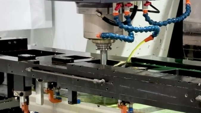
The complete setup defines the working area
Nominal axis travel describes machine movement. The usable machining area also depends on the part position, clamps, tool length, and head orientation.
The required X movement comes from the extreme tool-center positions along the planned paths. Cutter offsets, approach moves, and end-face access can extend those positions beyond the feature edges. Fixture components also restrict where the part can sit.
| Layout item | Dimensions or movements to check | Problem the check can reveal |
|---|---|---|
| X-axis coverage | First and last tool-center positions, approach, and overtravel | An end feature remains outside the reachable range |
| Profile and fixture width | Y movement, clamp width, and tool assembly clearance | Side cutting or edge milling causes interference |
| Fixture and profile height | Spindle-nose distances, tool length, and retract clearance | The tool cannot reach or retract safely |
| Tilted or angular tooling | Head housing, holder, and cutter envelope | The cutter reaches the face but the housing collides |
| Clamp movement | Clamp positions throughout the machining sequence | A clamp blocks a feature or leaves poor support |
Height affects both reach and clearance
A taller fixture may improve access to a side face, but it also reduces clearance above the part. A longer tool may reach a deep feature, but the holder can still strike the profile or a clamp.
Profile width mainly affects Y coverage in a conventional lengthwise setup. It does not automatically consume a fixed amount of X travel. The actual orientation determines the space needed.
A supplier should check the complete part, fixture, and tool assembly against the machine layout. A clearance check should include both ends and every required face. A trial cut can then confirm the features with the tightest access.
Welke frees- en tapbewerkingen vereisen meer dan alleen een hoog maximaal spiltoerental?
A fast spindle can still stall, vibrate, or damage taps under the wrong load. The demanding operations should determine the required torque, support, and control capability.
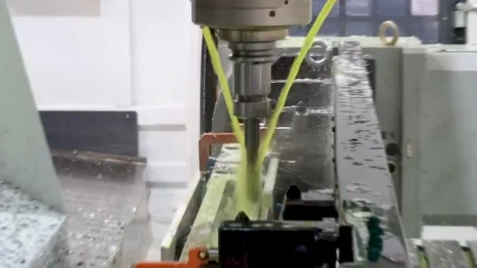
Wide slots, deep pockets, large holes, and larger threads require usable spindle torque, stable tooling, and effective chip removal. Thin walls require close support and controlled cutting forces. Rigid tapping also requires spindle and feed-axis synchronization through entry, reversal, and withdrawal. Maximum RPM does not establish these capabilities.
Cutting performance depends on the operating speed and setup
Spindle torque should be checked at the planned milling or tapping speed. The maximum power rating may describe a different operating point8. A trial should use the intended cutter engagement, tool overhang, profile supports, and chip-clearing arrangement.
Thin walls add another limit. A rigid machine can still deflect an unsupported profile wall9. Clamp position, support shape, tool sharpness, and cutting force all affect the result.
| Operatie | Capability beyond maximum RPM | Evidence from a trial |
|---|---|---|
| Wide slots or deep pockets | Available power and torque, stable engagement, chip removal | Stable load and acceptable slot size and finish |
| Thin-wall milling | Local support, controlled force, and suitable tooling | Wall thickness and shape remain within tolerance |
| Large-hole drilling or larger-thread tapping | Torque at the selected speed and effective lubrication | Stable cutting and conforming holes or threads |
| Rigid tapping | Coordinated spindle and feed-axis movement | Consistent thread quality through repeated cycles |
| Many scattered holes and tool changes | Axis response and complete sequence efficiency | Measured part cycle time |
Rigid tapping requires the correct relationship between rotation and feed
Rigid tapping advances the tool by one thread lead per spindle revolution10. For a standard single-start thread, the lead equals the pitch11.
In metric feed-per-minute programming, the relationship is F = n × P. F is the feed in mm/min, n is spindle speed in rpm, and P is pitch in mm. In feed-per-revolution programming, the commanded feed equals the pitch for that thread.
The controller must maintain synchronization during acceleration, reversal, and withdrawal. The supplier should confirm tapping capability for the actual thread size, material, depth, and holder.
A useful comparison includes the hardest recurring slot and thread on the production profile. Inspection should cover the least supported section. Timing should include tool changes and any clamp repositioning needed to complete the part.
Conclusie
A profile machining center earns its advantage through full feature access, stable support, fewer setups, and proven cutting performance across the actual long aluminum part.
-
"Vertical Machining Center (VMC) Technical Specifications:", https://www.rknec.edu/wp-content/uploads/2024/02/Spcifications_Vertical-Machining-Center.pdf. Standard VMCs typically offer X-axis travel ranging from 500mm to 1500mm, with larger models extending to 2000mm, though actual usable machining length is reduced by fixturing requirements and tool approach distances. Evidence role: general_support; source type: education. Supports: typical working area dimensions and travel ranges for standard vertical machining centers. Scope note: Specific capacity varies by manufacturer and model class ↩
-
"A Novel High-Precision Workpiece Self-Positioning Method for … – PMC", https://pmc.ncbi.nlm.nih.gov/articles/PMC12299440/. Manufacturing studies indicate that setup and changeover activities can account for 20-30% of total production time in multi-setup machining operations, with alignment verification adding measurable cycle time. Evidence role: general_support; source type: research. Supports: the productivity impact of multiple setups in CNC machining operations. Scope note: Actual impact varies with part complexity, tolerance requirements, and operator skill ↩
-
"CNC Trick to Machine a Massive 60” Part", https://www.youtube.com/watch?v=rA2vRwCFC3M. Technical literature on long-part machining identifies continuous features as particularly challenging because they require uninterrupted tool paths, consistent support along the cutting zone, and elimination of setup transitions that could create visible steps or alignment discontinuities in the finished feature. Evidence role: general_support; source type: research. Supports: the technical challenges of machining continuous features on long parts. Scope note: Specific challenges vary with feature type, tolerance requirements, and part material ↩
-
"CNC Router Engineering// Fixed VS. Moving Gantry", https://www.youtube.com/watch?v=ALvNohdBHb4. In machine tool design, configurations with stationary workpieces and moving cutting heads allow continuous support along the full workpiece length without requiring support structures to move with the table, reducing dynamic loads and simplifying fixturing for long, flexible parts. Evidence role: general_support; source type: education. Supports: the support advantages of stationary-workpiece machine configurations. Scope note: This advantage must be weighed against other factors including machine rigidity, thermal stability, and axis dynamics ↩
-
"Analysis of angular-error uncertainty in planar multiple-loop structures …", https://rpk.lcsr.jhu.edu/wp-content/uploads/2016/08/Li15_Analysis-of-Angular-Error-Uncertainty.pdf. In coordinate metrology, an angular misalignment of θ radians produces a lateral displacement of approximately L×θ at distance L from the pivot point, where small angles in radians equal the angle in degrees multiplied by π/180. Evidence role: mechanism; source type: education. Supports: how angular misalignment errors propagate with distance from a reference point. Scope note: This represents the geometric relationship; actual part deviation also depends on clamping compliance and thermal effects ↩
-
"ISO 230-2:2014 – Test code for machine tools — Part 2", https://www.iso.org/standard/55295.html. ISO 230-2 defines positioning repeatability as the closeness of agreement between repeated position measurements at the same target position under the same conditions, typically expressed as twice the standard deviation of position error. Evidence role: definition; source type: institution. Supports: the standardized definition and testing methodology for machine tool axis repeatability. Scope note: Standard test conditions may not reflect all variables present during actual production machining ↩
-
"A Robust Technique to Perform Product Quality Inspection", https://scholarworks.utrgv.edu/cgi/viewcontent.cgi?article=1947&context=etd. Quality control methodology for multi-setup machining emphasizes verification of datum-referenced dimensions and feature relationships that span setup boundaries, as these are most susceptible to accumulated positioning errors, with coordinate measuring machines or laser trackers often required for long parts where conventional inspection tools cannot span the full length. Evidence role: general_support; source type: institution. Supports: inspection methodology for parts machined in multiple setups. Scope note: Specific inspection requirements depend on drawing specifications and tolerance allocation ↩
-
"How to Use the Torque Chart to Optimize Your CNC Workflow", https://tormach.com/articles/how-to-use-the-torque-chart-to-optimize-your-cnc-workflow?srsltid=AYCX9vLaW7JmgfZZU7DTtXyVDAZZhWhwr6_uFs6h2a3ZAStWqxMclvLM. CNC spindle motors typically exhibit a constant-torque region at lower speeds and a constant-power region at higher speeds, with maximum power available only above a transition speed; below this speed, available power decreases proportionally with speed while torque remains constant. Evidence role: mechanism; source type: education. Supports: the relationship between spindle speed, torque, and available power in CNC machine tools. Scope note: Specific power and torque curves vary by spindle design and motor type ↩
-
"Analysis of the Displacement of Thin-Walled Workpiece Using a …", https://pmc.ncbi.nlm.nih.gov/articles/PMC8400720/. Research on thin-wall machining demonstrates that workpiece stiffness, rather than machine rigidity, often becomes the limiting factor when wall thickness falls below approximately 3-5mm in aluminum, with deflection magnitude depending on wall geometry, support spacing, and instantaneous cutting forces. Evidence role: mechanism; source type: research. Supports: the mechanism of thin-wall workpiece deflection under cutting forces. Scope note: Specific deflection behavior varies with alloy properties, wall geometry, and cutting parameters ↩
-
"What exactly is Rigid tapping? Why people always ask does it do …", https://www.cnczone.com/forums/general-metalwork-discussion/41856-cnc.html. Rigid tapping, also called synchronous tapping, is a CNC machining method where the controller maintains precise synchronization between spindle rotation and Z-axis feed throughout the tapping cycle, eliminating the need for tension-compression tap holders by ensuring the feed rate exactly matches the thread pitch multiplied by spindle speed. Evidence role: definition; source type: education. Supports: the technical definition and operating principle of rigid tapping. ↩
-
"ISO metric screw thread", https://en.wikipedia.org/wiki/ISO_metric_screw_thread. In screw thread terminology, the lead is the axial distance a threaded part advances in one complete revolution, while pitch is the distance between corresponding points on adjacent threads; for single-start threads, lead equals pitch, but for multi-start threads, lead equals pitch multiplied by the number of starts. Evidence role: definition; source type: encyclopedia. Supports: the relationship between thread lead and pitch in single-start threads. ↩

Chris Lu
Met meer dan tien jaar praktijkervaring in de werktuigmachine-industrie, vooral met CNC-machines, ben ik er om je te helpen. Of je nu vragen hebt naar aanleiding van dit bericht, begeleiding nodig hebt bij het selecteren van de juiste apparatuur (CNC of conventioneel), aangepaste machineoplossingen onderzoekt of klaar bent om een aankoop te bespreken, aarzel niet om contact met mij op te nemen. Laten we de perfecte bewerkingsmachine voor uw behoeften vinden.