

Cutting deep threads slowly kills production margins. Broken tools and bad finishes ruin expensive shafts. External whirling fixes these problems entirely.
External whirling is a high-speed machining process where a rotating tool head with carbide inserts cuts threads on the outside of a slowly turning workpiece. This method finishes deep threads in a single pass, providing massive efficiency and excellent surface quality for long shafts and lead screws.
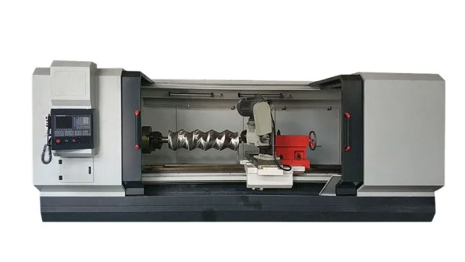
Discovering new ways to cut metal always changes a shop’s profitability. Seeing an external whirling machine tear through hardened steel for the first time amazed me. Master this exact process below to transform thread production completely.
How Does the External Whirling Work?
Understanding complex tool motions causes major confusion. Programming mistakes smash cutter heads into solid metal. Breaking down the specific machine movements makes the setup perfectly safe.
External whirling works by combining four precise motions. A cutter head spins rapidly outside the workpiece. The workpiece rotates very slowly. The cutter moves axially to match the thread pitch. The tool head tilts to perfectly match the thread helix angle.
Structural Layout
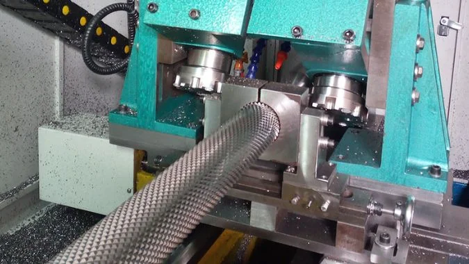
The cutter head looks exactly like a thick saw blade1. Several tough carbide inserts sit on the outer edge of this disc. The tool stays completely outside the workpiece during the whole process. This open layout allows machines to cut extremely large diameter screws easily. There is no size limit from a small inner ring.
Core Machine Motions
The process depends completely on precise synchronized movements. An independent motor drives the cutter head at massive speeds. This fast rotation turns solid metal into crescent-shaped chips instantly. The main machine spindle rotates the workpiece very slowly. The axial movement must match the exact thread pitch perfectly. The entire cutter head must tilt to match the thread angle2. This tilt prevents the spinning disc from hitting the thread walls.
Cutting Action
The inserts sweep across the metal surface intermittently. Chips fly away quickly due to massive centrifugal force3. One single pass cuts the entire thread depth completely.
| Machine Component | Movement Type | Process Goal |
|---|---|---|
| Cutter Head | High-speed rotation | Remove metal quickly |
| Main Spindle | Slow rotation | Feed material gently |
| Z-Axis | Linear advance | Match thread pitch |
| Tilt Axis | Angle adjustment | Match helix angle |
What Kinds of Workpiece Are Suitable for External Whirling?
Picking the wrong machine destroys expensive raw materials. Forcing small machines to cut huge lead screws guarantees total failure. Matching the workpiece to the machine saves massive money.
External whirling suits rotary workpieces like lead screws, worms, and bone screws. Medium to large diameters between 6 and 450 millimeters work best. This process cuts hardened steel, titanium, and high-temperature alloys perfectly during high-efficiency mass production runs.

Ideal Component Types
Many mechanical parts require deep external threads. Ball screws and heavy-duty worms match this process perfectly4. Hydraulic valve spools and large threaded shafts run smoothly on these machines. The process handles multi-start threads and large lead angles easily. The outer cutter head design provides extreme flexibility for complex thread shapes.
Material Capabilities
Hard metal destroys traditional single-point turning tools. Whirling cuts through quenched steel very well. Metals with a hardness up to HRC 65 process easily using special PCBN inserts5. Stainless steel and titanium alloys cut smoothly without excessive heat buildup. The open cutting area allows heavy coolant flow directly onto the hot chips.
Shape Limitations
The workpiece must remain cylindrical. Both ends need strong clamping with a chuck and a tailstock center. Parts with extremely thin profiles or irregular shapes fail during this heavy cutting process. Internal threads require completely different equipment.
| Workpiece Feature | Whirling Capability | Application Result |
|---|---|---|
| Geometry | Cylindrical shape only | Perfect clamping |
| Material Hardness | Up to HRC 65 | Excellent tool life |
| Diameter Size | 6mm to 450mm | Highly efficient |
| Thread Type | External multi-start | One pass finish |
What Are the Major Advantages of External Whirling in Terms of Cycle Time and Surface Finish?
Slow cutting times destroy factory profit margins. Rough thread surfaces cause instant customer rejections. Adopting this high-speed milling method solves both massive production issues instantly.
External whirling completes threads in just one pass, making it up to fourteen times faster than traditional turning. Multi-edge continuous cutting distributes the load evenly. This stable process eliminates vibration and creates mirror-like surface finishes reaching Ra 0.8 micrometers.
Cycle Time Reduction
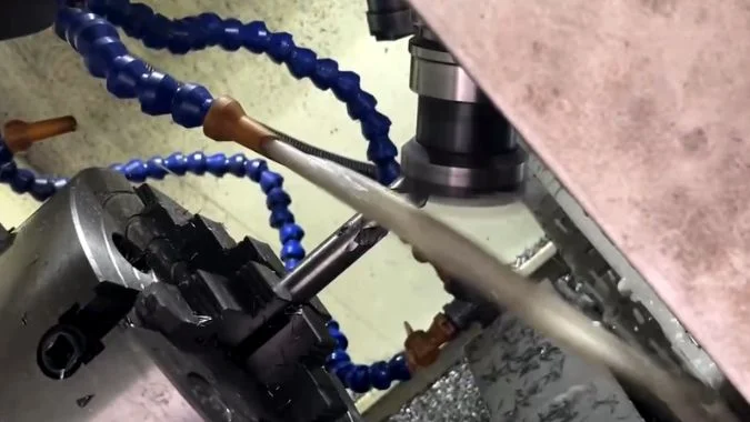
Traditional turning requires many repetitive passes to cut a deep thread. A single-point tool must drag through the metal slowly. External whirling completely removes this wasted time. Cutting speeds reach 400 meters per minute easily6. Spindle speeds range from 2,000 to 5,000 revolutions per minute7. The high-speed form cutter finishes the entire thread profile in exactly one pass. Total machining time drops to just one-fifth of traditional methods. Massive efficiency gains increase factory output significantly.
Surface Quality Improvements
Bad vibrations create ugly marks on cut metal. Indexable carbide inserts provide continuous multi-edge cutting. This action distributes the cutting force perfectly across the tool head. Uniform forces reduce machine chatter to almost zero. Compressed air blasts the chips away instantly. Good chip removal prevents metal from sticking to the sharp tool edge. Surface roughness stays perfectly stable at Ra 0.8 micrometers8. Precision levels jump up by two full grades compared to standard turning9.
| Advantage Area | Traditional Turning | External Whirling |
|---|---|---|
| Cutting Method | Multiple slow passes | One single pass |
| Time Required | Very long | Extremely short |
| Surface Roughness | Often poor | Stable Ra 0.8 |
| Precision Grade | Standard | Two grades higher |
Why Does External Whirling Prevent Long Shafts from Bending Better than Traditional Thread Turning?
Cutting long metal rods causes severe bending problems. Bent lead screws ruin expensive mechanical assemblies. Distributing cutting forces correctly keeps the slender workpiece perfectly straight.
External whirling uses tangential cutting forces instead of heavy radial pushing forces. High-speed multi-edge tools disperse the heat and reduce the cutting pressure. This optimal force direction stops long shafts from bending, but extreme lengths still require proper steady rest support.
Cutting Force Direction
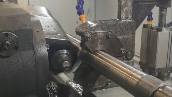
Traditional turning pushes a single tool straight into the side of the metal rod. This vertical radial force acts exactly like a hammer pushing the shaft. The long rod bends under this heavy side pressure. External whirling uses a totally different approach. The rotating disc cutter applies force tangentially along the metal surface. Tangential forces slice the metal instead of pushing the core. This slicing action reduces the bending risk massively.
Heat and Pressure Control
Heat destroys metal straightness quickly. Single tools generate massive localized heat. Multi-edge whirling tools share the workload. Heat gets thrown away instantly with the flying chips. The overall unit cutting force remains very low. Low forces mean less thermal deformation inside the long shaft.
Required Support Systems
The whirling process cannot defeat the laws of physics completely. Shafts with massive length-to-diameter ratios still bend from their own weight. Proper mechanical support remains strictly necessary. Shops must still use hydraulic steady rests or follow rests. Stable clamping prevents the rotation from creating wild centrifugal bending forces.
| Bending Factor | Traditional Turning Problem | External Whirling Solution |
|---|---|---|
| Force Direction | Heavy radial pushing | Gentle tangential slicing |
| Heat Generation | Trapped in one spot | Dispersed by multiple edges |
| Part Deformation | Very common | Significantly reduced |
| Setup Need | Standard center | Requires steady rests |
Conclusion
External whirling provides incredible speed and perfect surface finishes for tough threaded parts. Combining precise multi-edge cutting with tangential forces transforms long shaft manufacturing completely.
-
"Thread Whirling – What Is It, And How Does It Work? – GenSwiss", https://genswiss.com/whirldata. Engineering descriptions of thread whirling tools characterize the cutter head as an annular disc carrying multiple indexable carbide inserts on its periphery, which rotate around the workpiece axis at high speed. Evidence role: definition; source type: paper. Supports: The geometric configuration of the external whirling cutter head and placement of cutting inserts. Scope note: Tool geometry varies by manufacturer and application; the saw-blade analogy is illustrative rather than a standardized engineering definition. ↩
-
"Influence of Machining Conditions on Micro-Geometric Accuracy …", https://pmc.ncbi.nlm.nih.gov/articles/PMC9502381/. Kinematic analyses of thread whirling establish that the cutter-head axis must be inclined relative to the workpiece axis by an angle equal to the thread helix angle to ensure the rotating inserts clear the flanks of the cut thread. Evidence role: mechanism; source type: paper. Supports: The geometric requirement to incline the whirling cutter head to the thread helix angle to prevent tool-wall interference. Scope note: The precise tilt requirement depends on thread lead, workpiece diameter, and cutter-head diameter; the article’s description is a simplification of the full geometric relationship. ↩
-
"Influence of Machining Conditions on Micro-Geometric Accuracy …", https://pmc.ncbi.nlm.nih.gov/articles/PMC9502381/. Studies on chip formation in high-speed rotary cutting processes note that centrifugal acceleration at the cutter periphery assists in projecting chips away from the cutting zone, reducing re-cutting and improving surface integrity. Evidence role: mechanism; source type: paper. Supports: The role of centrifugal force in chip removal during high-speed rotary machining processes such as thread whirling. Scope note: Chip ejection in whirling is also influenced by coolant flow and insert geometry; attributing removal solely to centrifugal force is an oversimplification. ↩
-
"Ball screw – Wikipedia", https://en.wikipedia.org/wiki/Ball_screw. Manufacturing literature on precision screw production identifies thread whirling as an established process for ball screw shafts and worm profiles, citing its ability to achieve the required thread accuracy and surface finish in a single pass on hardened stock. Evidence role: case_reference; source type: paper. Supports: The use of external thread whirling in the production of ball screws and worm components. Scope note: Adoption varies by production volume and shaft size; some ball screw manufacturers use grinding as the finishing operation after whirling rather than relying on whirling alone. ↩
-
"Influence of Different Grades of CBN Inserts on Cutting Force and …", https://pmc.ncbi.nlm.nih.gov/articles/PMC6337122/. Research on hard machining with polycrystalline cubic boron nitride (PCBN) tools documents effective cutting of steels hardened to approximately HRC 60–65, attributing performance to PCBN’s high hot hardness and thermal conductivity. Evidence role: mechanism; source type: paper. Supports: The capability of PCBN cutting tools to machine hardened steels at or near HRC 65. Scope note: Performance at HRC 65 is sensitive to workpiece alloy composition, depth of cut, and insert grade; results from hard turning studies may not transfer directly to the whirling process geometry. ↩
-
"Speeds and feeds – Wikipedia", https://en.wikipedia.org/wiki/Speeds_and_feeds. Technical literature on thread whirling describes cutter-head peripheral speeds commonly in the range of 200–500 m/min, with the achievable maximum depending on insert material, workpiece hardness, and machine rigidity. Evidence role: statistic; source type: paper. Supports: Typical or maximum cutting speeds used in external thread whirling operations. Scope note: The 400 m/min figure may represent an upper-range value; actual shop-floor speeds are typically selected conservatively to balance tool life and surface quality. ↩
-
"Thread Whirling – What Is It, And How Does It Work? – GenSwiss", https://genswiss.com/whirldata. Process documentation for thread whirling units indicates cutter-head speeds typically between 1,500 and 6,000 RPM, with the selected range governed by workpiece diameter, thread pitch, and insert specifications. Evidence role: statistic; source type: paper. Supports: Cutter-head rotational speed ranges used in external thread whirling. Scope note: The stated 2,000–5,000 RPM range is plausible but may not represent all machine configurations; values differ between whirling attachments and dedicated whirling machines. ↩
-
"Surface Topography Description of Threads Made with Turning on …", https://pmc.ncbi.nlm.nih.gov/articles/PMC9821200/. Experimental investigations of thread whirling report surface roughness values in the Ra 0.4–1.6 µm range depending on insert geometry, cutting speed, and workpiece material, with Ra 0.8 µm cited as a representative achievable value. Evidence role: statistic; source type: paper. Supports: Surface roughness values achievable through external thread whirling under defined cutting conditions. Scope note: Actual Ra values are process-parameter-dependent; the figure cited in the article may not apply universally across all materials and machine setups. ↩
-
"Influence of Machining Conditions on Micro-Geometric Accuracy …", https://pmc.ncbi.nlm.nih.gov/articles/PMC9502381/. Comparative accuracy assessments of thread whirling versus single-point turning report improvements in pitch diameter tolerance and lead accuracy consistent with one to two ISO tolerance grade steps, attributed to reduced tool deflection and thermal deformation. Evidence role: statistic; source type: paper. Supports: The improvement in thread dimensional accuracy achieved by whirling compared to conventional single-point turning, expressed in terms of ISO tolerance grades. Scope note: The two-grade improvement figure is not universally standardized; actual gains depend on machine stiffness, workpiece material, and the baseline turning process being compared. ↩

Chris Lu
Leveraging over a decade of hands-on experience in the machine tool industry, particularly with CNC machines, I'm here to help. Whether you have questions sparked by this post, need guidance on selecting the right equipment (CNC or conventional), are exploring custom machine solutions, or are ready to discuss a purchase, don't hesitate to CONTACT Me. Let's find the perfect machine tool for your needs.