

Why Does One Insert Wear Out First in a Thread Whirling Cutter Ring?
One insert wearing early can interrupt production and damage the thread profile. Comparing its installed position and wear pattern helps identify why it differs from the others.
In a thread whirling cutter ring with matching inward-facing inserts, one insert can wear first because it projects farther into the cut, seats incorrectly, or suffers localized heat or impact. Repeated wear in the same pocket makes cutting-edge position, seating, and clamping the first checks.
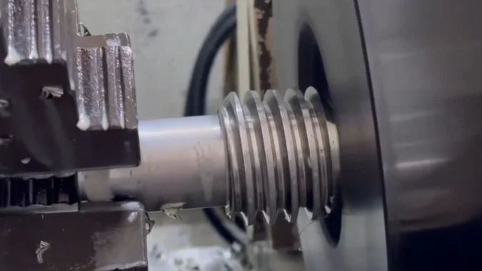
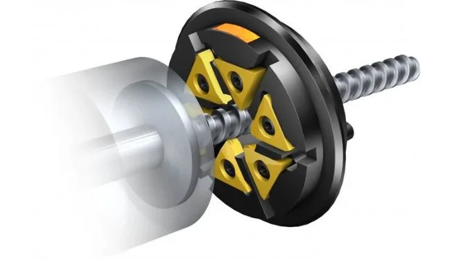
The cutter ring in this discussion carries form inserts with cutting edges facing the central opening. The workpiece passes through that opening for external thread machining. Each insert rotates into and out of engagement. The first diagnostic step is to establish how those matching edges are intended to share the cutting work.
Are All Inserts in the Whirling Cutter Ring Designed to Carry the Same Load?
Matching inserts should contribute similar cutting work. A persistent difference can shorten tool life, so the intended arrangement needs checking before cutting parameters are changed.
Matching form inserts in this type of cutter ring are intended to share similar cutting work. Their instantaneous loads change during engagement, but one insert should not consistently take an unintended extra share. A fair comparison requires the same profile, grade, edge condition, and cutting history.
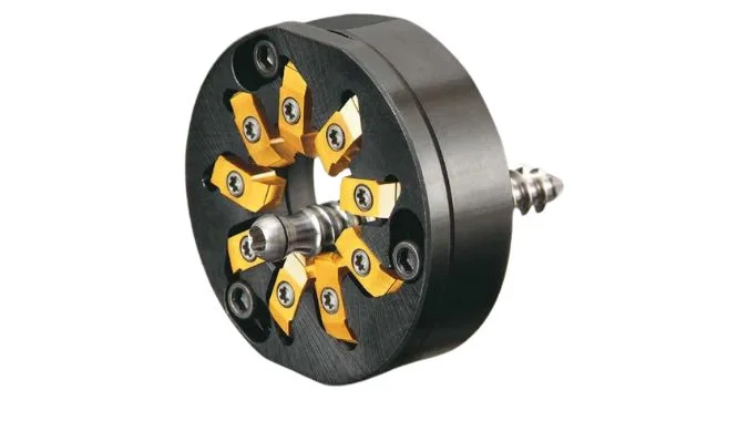
Matching form inserts provide the reference
The inserts are mounted around the inside of the cutter ring. Their cutting edges face the opening and generate the external thread as the cutter ring rotates around the workpiece.
The intended cutting relationship depends on the specified edge positions. A tip that projects farther toward the opening can engage more material than intended. A tilted or poorly supported insert can also rub or experience greater impact.
| Item to confirm | Why it matters |
|---|---|
| Insert profile and part number | Matching pockets need the specified cutting geometry |
| Grade and edge preparation | Different edge conditions can produce different wear rates |
| Installed tip position | A projecting edge may take more of the cut |
| Previous cutting exposure | An older edge can appear to fail early in the current batch |
Every insert passes through the entry region
Each insert enters and leaves the cutting region as the cutter ring rotates. A fixed pocket does not remain permanently at the point where cutting begins.
High cutting speed or heavy engagement can increase the demands on the whole set. These conditions alone do not establish why one particular pocket repeatedly wears first. That pattern needs a check for differences in seating, cutting-edge position, or support.
The cutter ring drawing should establish the intended insert arrangement. The diagnosis should begin with that arrangement and the actual installed geometry.
What Wear Pattern Suggests That One Insert Is Cutting More Material?
A wider wear band can reveal uneven engagement, but it does not establish the cause. Consistent inspection helps separate heavier cutting from rubbing or poor cooling.
A wider flank wear land developing faster on one matching insert suggests heavier engagement or greater rubbing. Faster nose wear or a deeper rake-face crater can support the suspicion. Actual edge-position measurements are needed because wear differences can also result from cooling, grade, or edge damage.
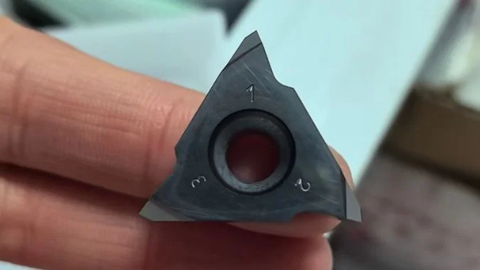
Flank wear is the most useful starting comparison
The flank wear land is the band of material loss behind the cutting edge. Its width is commonly recorded as VB1.
The operator should inspect the same area on each matching insert. A 10× magnifier can support the first comparison2. Photographs taken at the same magnification help track how quickly the band grows.
The inserts should have comparable cutting exposure. Comparing a new edge with one already used on an earlier job can produce a misleading result.
| Wear pattern | What it may suggest | Supporting check |
|---|---|---|
| Wider, continuous flank wear | Greater cutting exposure or rubbing | Tip position and flank clearance |
| Faster nose rounding | Concentrated loading near the profile tip | Seating and actual profile engagement |
| Deeper rake-face crater | Higher local thermal demand | Coolant delivery, grade, and cutting speed |
| Jagged missing sections | Local edge fracture | Impact, vibration, clamping, and chip clearance |
Wear measurements need a supporting position check
A projecting insert can remove extra material on successive revolutions. A wrongly seated insert may instead wear quickly because its clearance has changed. Both can produce a larger wear land, but they require different corrections.
Increasing burrs, thread-profile drift, and a gradual loss of surface finish provide supporting evidence. Machine load and noise describe the combined process and cannot identify one insert’s cutting volume by themselves.
Wear limits should follow the insert supplier’s guidance and the thread’s quality requirements. A general milling wear limit should not automatically become the replacement limit for a precision thread-whirling job.
What Should Be Checked When the Same Insert Pocket Always Wears First?
Repeated wear in one pocket wastes replacement inserts and suggests a repeatable local difference. Seating, clamping, and assembled edge position should be checked first.
The suspect pocket needs checks for trapped chips, damaged locating surfaces, incorrect seating, and clamp or screw problems. The assembled cutting-edge positions, cutter ring mounting, and runout need verification next. Continued early wear with a fresh matching insert strengthens the case for a pocket-related problem.
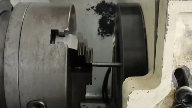
The pocket and clamp come first
The operator should record the pocket number and the insert fitted there. The inspection should take place with the machine stopped and the cutter ring handled through its specified service procedure.
A chip beneath the insert can change its position3. A nick or damaged locating surface can prevent full contact. A worn clamp or screw can allow movement during the repeated entry and exit of cutting.
The replacement insert should have the specified profile and orientation. Tightening should follow the prescribed torque and sequence4. A setting fixture can improve consistency on cutter rings designed for insert replacement outside the machine.
| Inspection point | Evidence to look for |
|---|---|
| Pocket locating surfaces | Trapped material, nicks, deformation, or incomplete contact |
| Clamp and screw | Damage, poor engagement, or inconsistent retention |
| Insert position | A tip that projects or tilts beyond its specified position |
| Cutter ring mounting interface | Dirt, damage, or incomplete seating |
| Assembled cutter ring and cutting edges | Radial or axial variation beyond the specified limits |
Cutting-edge position needs its own check
A measurement of the cutter ring’s outside diameter cannot establish that every cutting tip is correctly positioned. The assembled cutting edges need checking through the cutter ring manufacturer’s measurement procedure.
Runout should be measured at the specified reference surfaces5. The acceptance limit depends on the cutter ring and application. The intentional cutter-ring-to-workpiece offset is a separate setup parameter and should match the process specification.
A fresh matching insert and correct reseating provide a controlled comparison. Cutting conditions and exposure should remain consistent during that comparison. Continued early wear in the same pocket calls for closer inspection of the seat and cutter ring geometry.
The later checks should include chip clearance, coolant delivery, mounting rigidity, and spindle bearing condition. Cutting-speed changes can reduce excessive thermal demand, but they cannot restore a damaged locating surface.
How Can Chip Damage Be Distinguished from Normal Cutting-Edge Wear?
An edge that loses carbide needs a different response from one that wears gradually. Damage shape and its development help identify the next corrective action.
Progressive wear usually produces a continuous flank wear band or smooth rake-face erosion. Chipping produces localized missing carbide, jagged notches, or broken corners. Chip impact is one possible cause, but vibration, overload, and thermal fatigue also need checking. Shape alone cannot establish the cause.
Progressive wear and local fracture leave different evidence
A continuous wear band can grow over many parts. A chipped edge contains missing tool material and a disrupted cutting profile. Both conditions can exist on the same insert.
The operator should inspect the cutting edge and nearby surfaces under magnification. A small notch in the profile can matter even before a broad wear band develops.
| Appearance | Likely condition | Useful follow-up check |
|---|---|---|
| Continuous, gradually widening flank band | Progressive flank wear | Wear rate, cutting conditions, and clearance |
| Smooth rake-face crater | Progressive rake-face wear | Heat, chip contact, and remaining edge strength |
| Jagged gaps or a missing corner | Chipping or fracture | Seating, engagement, impact, and vibration |
| Repeated cracks across the edge | Possible thermal fatigue | Temperature cycling and coolant consistency |
| Impact marks outside the active cutting area | Possible chip contact | Trapped chips and the evacuation path |
Chip impact needs supporting evidence
Chips caught in the cutter ring can strike an edge or be cut again6. Trapped material, impact marks, and damage near the affected edge support that explanation.
Chipping alone does not prove chip impact. A projecting insert, unstable clamping, or chatter can also fracture the edge. Thermal cracks may develop over repeated cycles before a section breaks away.
The process history helps distinguish these conditions. Gradually worsening finish and steadily increasing wear suggest progressive deterioration. An abrupt thread defect or new noise can accompany edge fracture.
Chip shape provides another clue, but serrated or fragmented chips7 alone cannot confirm tool damage. The cutting edge must be inspected directly.
A regular wear band can be expected during tool use, but an unusually fast wear rate still needs investigation. The corrective action should address the measured condition before another insert is put through the same cycle.
Conclusion
Early single-insert wear needs checks of seating, cutting-tip position, and pocket repeatability. Comparable wear records and direct inspection help distinguish uneven engagement from rubbing or fracture.
-
"A Novel Tool Condition Monitoring Technique of Determining …", https://pmc.ncbi.nlm.nih.gov/articles/PMC12566434/. ISO 3685 defines VB as the measurement of average flank wear land width, a primary indicator of cutting tool condition in machining operations. Evidence role: definition; source type: institution. Supports: VB is the standardized symbol for average flank wear land width in tool wear measurement. ↩
-
"Quantifying Wear and Service Life of Tooling", https://www.keyence.com/products/microscope/digital-microscope/industries/automotive/tool-wear.jsp. Machining handbooks typically recommend 10× to 20× magnification for initial visual assessment of flank wear and edge condition in production environments, with higher magnification reserved for detailed laboratory analysis. Evidence role: general_support; source type: education. Supports: Low-power magnification (10×–20×) is commonly recommended for field inspection of cutting tool wear. Scope note: Recommendation varies by insert size and required measurement precision ↩
-
"Troubleshooting", https://www.sandvik.coromant.com/en-us/knowledge/general-turning/troubleshooting-turning. Machining references identify trapped chips or debris in insert pockets as a common cause of improper seating, which alters cutting geometry and accelerates wear through increased mechanical and thermal stress. Evidence role: mechanism; source type: education. Supports: Foreign material in insert pockets is a recognized cause of improper seating and premature tool failure. ↩
-
"Carbide inserts torque? : r/Machinists", https://www.reddit.com/r/Machinists/comments/v44xvs/carbide_inserts_torque/. Studies of indexable insert systems demonstrate that insufficient or excessive clamping torque can cause insert movement, accelerated wear, or fracture; manufacturers specify torque values to ensure adequate clamping force without overstressing the carbide. Evidence role: mechanism; source type: research. Supports: Proper clamping torque is critical for insert stability and cutting performance. Scope note: Optimal torque values are insert-system-specific and must be obtained from the tool manufacturer ↩
-
"What Is Runout in Machining? Causes and How to Reduce It", https://taigtools.com/blog/runout-in-machining/. Machine tool standards recognize runout as a critical parameter affecting cutting tool performance; excessive radial or axial runout causes uneven insert engagement, accelerated wear, and poor surface finish. Evidence role: general_support; source type: institution. Supports: Runout measurement is a standard quality check for rotating cutting tools. Scope note: Acceptable runout limits depend on application precision requirements and are typically specified by the tool manufacturer ↩
-
"Chip Recutting – In the Loupe Machinist Blog", https://www.harveyperformance.com/in-the-loupe/tag/chip-recutting/. Machining literature identifies inadequate chip evacuation as a source of tool damage; trapped chips may be recut—increasing cutting forces—or strike tool surfaces, causing impact damage, particularly in enclosed cutting geometries where chip flow is restricted. Evidence role: mechanism; source type: education. Supports: Poor chip evacuation can cause tool damage through recutting and impact. ↩
-
"Forming process and evaluation of chip in machining of high …", https://pmc.ncbi.nlm.nih.gov/articles/PMC10450704/. Metal cutting research establishes that chip shape and segmentation result from material properties, cutting conditions, and tool geometry; serrated chips indicate cyclic shear localization, while chip fragmentation patterns can reveal vibration, material inhomogeneity, or unfavorable cutting parameters. Evidence role: general_support; source type: research. Supports: Chip morphology reflects cutting mechanics and material behavior. Scope note: Chip morphology alone cannot diagnose specific tool wear mechanisms without direct edge inspection ↩

Chris Lu
Leveraging over a decade of hands-on experience in the machine tool industry, particularly with CNC machines, I'm here to help. Whether you have questions sparked by this post, need guidance on selecting the right equipment (CNC or conventional), are exploring custom machine solutions, or are ready to discuss a purchase, don't hesitate to CONTACT Me. Let's find the perfect machine tool for your needs.