

Why Does the Wire Break on the Second Cut in MS-WEDM?
A successful rough cut can still end in a broken wire during trimming. Comparing the two passes helps identify the changed condition before another restart.
Second-cut wire breakage can result from a closing kerf, damaged molybdenum wire, unsuitable trim settings, worn power feed contacts, or poor flushing. Roughing can change the workpiece and wire before trimming starts. The failure needs checks of both mechanical clearance and discharge conditions.
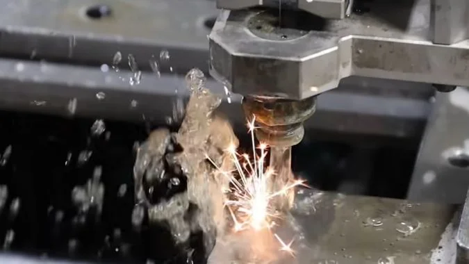
The rough cut reached the end, but the wire broke shortly after trimming began. That sequence gives the operator a useful comparison. The machine completed one set of conditions and failed under another. The inspection should start with the workpiece, wire, and setup as they stood between those two passes.
What Changed Between the Successful Rough Cut and the Failed Second Cut?
The first pass proves that roughing was possible. It does not prove that trimming conditions remain sound, so the transition between passes needs a separate inspection.
The rough cut can change kerf clearance, workpiece shape, scrap support, wire condition, and debris levels. The second cut also uses a different path offset and discharge settings. Any handling or rethreading between passes can introduce another change that affects wire clearance or stability.
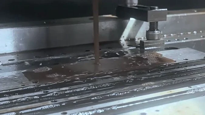
The workpiece and kerf may have changed
Rough cutting removes material that helped hold the blank in its original shape. Residual stress can then distort a thin wall or narrow section1. A kerf that was open during roughing may become tight enough to pinch the wire.
The cut-out material also needs attention. A loose or partly attached slug can lean into the wire path. Scrap removal must follow the planned support and retention sequence because removing it can also change the setup.
| Item to compare | Change after roughing | Evidence to inspect |
|---|---|---|
| Kerf and thin sections | Local clearance may decrease | A narrowed slot, contact marks, or repeated short circuits |
| Cut-out material | A slug may shift or remain trapped | Its position and remaining attachment points |
| Molybdenum wire | Wear or local damage may increase | Diameter variation, scoring, or visible weak sections |
| Working fluid | Debris may remain in the kerf | Filter condition and fluid delivery at the cut |
| Trim program | Offset and electrical settings change | The selected pass, compensation, and entry path |
The transition should be reconstructed
The operator should record what happened after roughing. The useful details include scrap handling, cleaning, clamp adjustments, wire replacement, and parameter changes.
Rethreading is a check where the process requires it; it is not an automatic requirement for every trim pass. The wire must follow the intended guide route and enter a clear path.
A lower-energy trim setting cannot prevent a mechanical break in a closing kerf. The comparison should establish clearance before electrical adjustments begin.
Can Wire Damage from the Rough Cut Contribute to Second-Pass Breakage?
A wire can complete roughing with damage that reduces its remaining strength. Carrying that condition into trimming can turn a weak section into the next break.
Wire damage from roughing can contribute to second-pass breakage. Reused molybdenum wire can carry erosion, thinning, or mechanical damage into trimming. A weakened section may fail under tension or unstable discharge. Inspection must include the contacts and guides that could damage it again.
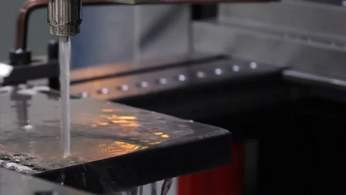
Reused wire carries its previous condition forward
Medium-speed wire EDM commonly reuses molybdenum wire through repeated travel2. The wire entering the trim cut may already have experienced substantial discharge exposure.
Aggressive roughing conditions and poor debris removal can increase local heating and erosion3. A damaged section has less margin against the combined effects of tension, friction, and further discharge.
The inspection should cover more than the short piece beside the break. Other sections of the working wire may also be worn. Diameter checks at several positions can help reveal uneven thinning, but the acceptance limit must match the wire and machine specification.
| Observation | Possible contributor | Next check |
|---|---|---|
| Uneven thinning or eroded sections | Discharge wear accumulated during roughing | Roughing conditions, flushing, and wire suitability |
| Scratches along the wire | Contact with a damaged guide or power feed contact | Contact surfaces and the complete wire route |
| Breaks near a guide | Friction, misalignment, or guide damage | Guide rotation, groove condition, and alignment |
| Fresh wire breaks at the same contour location | A local kerf, path, or flushing problem remains | The workpiece and conditions at that location |
Replacement must address the source of damage
A grooved power feed contact can scratch the wire or interfere with its travel4. Worn guide wheels and bearings can also disturb wire motion and tension. These components need inspection before replacement wire returns to service.
A successful retry with fresh wire supports the possibility that the old wire contributed. A repeat break at the same workpiece location points toward an unresolved local condition. Neither result should replace an inspection of the full process.
How Can Workpiece Movement After Rough Cutting Be Ruled Out?
Small workpiece changes can close the trim clearance without an obvious clamp failure. Measurements are needed to separate local distortion from movement of the whole part.
Workpiece movement can be checked by comparing established reference features before and after roughing. The inspection must separate clamp slip from local deformation and confirm clearance near the failed cut. Marker lines reveal large shifts, but they cannot rule out small changes that matter during trimming.
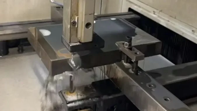
Clamp slip and deformation leave different evidence
A part can remain firmly clamped and still change shape. Residual stress release may bend a thin section while the main clamping area stays in place.
Clamp slip changes the position of the part relative to the fixture. Local deformation changes the relationship between features within the part. The two conditions need different corrective actions.
A useful measurement plan records stable reference features before roughing. The same features can then be checked after roughing with a suitable indicator, probe, or inspection method.
| Check | What it helps establish | Limitation |
|---|---|---|
| Witness marks across the part and fixture5 | Whether a large relative shift occurred | Marks do not resolve small positional changes |
| Repeated checks of clamping references | Whether the part shifted in the fixture | Stable references do not prove that thin walls stayed straight |
| Measurements near the failed contour | Whether local geometry or clearance changed | The original reference or intended geometry must be known |
| Inspection of clamps and supports | Whether retention remains secure | Tight fasteners alone do not prove unchanged geometry |
The evidence should cover the failed region
The operator should inspect corners, narrow bridges, thin walls, and the position of the cut-out material. A stable clamping reference cannot exclude a closing kerf elsewhere on the part.
An inspection started only after failure cannot establish the earlier position from marker lines alone. The operator should compare available reference records and verify the remaining stock and clearance.
Any clamp change can alter the part position again, so the reference checks must be repeated after adjustment. Additional support should hold the part without forcing a distorted section into a temporary shape.
Machine positioning can be investigated if the fixture and part checks remain consistent. Axis return errors are a separate issue6 from workpiece slip and should be checked through the machine’s approved procedure.
What Must Be Verified Before Retrying the Failed Trim Pass?
Rethreading without correcting the fault can repeat the break and damage the contour. A controlled restart needs verified clearance, wire travel, fluid condition, and trim settings.
Before retrying, the operator must verify an open wire path, secure workholding, serviceable wire, stable tension, sound guides and power feed contacts, effective flushing, and the correct trim program. The restart position and compensation must follow the machine’s recovery procedure and the remaining machining allowance.
The break location should guide the inspection
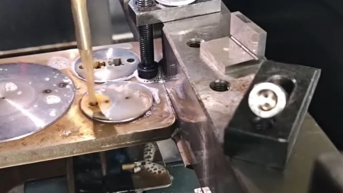
The operator should preserve the failure position and available alarm history before resetting the job7. Repeated short circuits near a thin wall suggest a clearance problem, but they can also accompany debris buildup. A break near a guide directs attention to wire travel and contact surfaces.
Broken wire and trapped debris need removal with the machine in the condition specified for cleaning8. The kerf and guides must be clear before the wire returns to the cutting zone.
| Verification | Evidence needed before retrying |
|---|---|
| Workpiece and scrap | Secure retention and clearance along the restart path |
| Wire condition | A suitable wire diameter and no unacceptable damage |
| Tension and travel | Stable operation without catching, jumping, or abnormal vibration |
| Contacts and guides | Serviceable surfaces, smooth rotation, and correct alignment |
| Working fluid | Suitable condition, effective filtration, and delivery into the kerf |
| Trim settings | The correct pass settings for material, thickness, and wire |
| Recovery path | Confirmed position, compensation, and remaining stock |
Settings must match the actual machine and consumables
The fluid concentration should follow the approved fluid supplier’s range. A refractometer reading must be interpreted using that product’s measurement instructions9. One concentration range cannot be transferred to every medium-speed EDM fluid.
Wire tension and travel speed also need the machine’s specified values10. The check should include actual stability because a correct setpoint does not prove smooth wire motion.
The selected trim conditions should include the intended pulse width, peak current, pulse interval, and tracking settings11. Roughing settings should not carry into trimming through an overlooked program selection.
Recovery must preserve the remaining contour
The restart position and offset need checking against the completed portion of the pass. Wire replacement can also require a review of the diameter used for compensation.
A fixed retreat distance or added offset cannot suit every failed trim cut12. The recovery procedure must account for the current position, cut direction, and remaining allowance. The first resumed section should be monitored for stable discharge and smooth travel before the job continues.
Conclusion
Second-pass breakage needs a comparison with roughing conditions. Verified kerf clearance, workpiece stability, wire condition, flushing, and trim settings provide a sound basis for retrying.
-
"Thin-Wall Machining Mistakes: Residual Stress and More", https://www.linkedin.com/posts/mohammadzandindustrial_thinwallmachining-cncmachining-manufacturingengineering-activity-7465162084973002752-QQWs. Material removal during machining can release residual stresses that were balanced in the original workpiece, leading to distortion particularly in thin-walled or flexible geometries where structural rigidity is insufficient to resist the stress redistribution. Evidence role: mechanism; source type: research. Supports: Residual stress release can cause dimensional changes in thin-walled machined components. Scope note: General machining principle; specific magnitude of distortion in wire EDM depends on material properties, geometry, and cutting parameters ↩
-
"Molybdenum Wire for EDM: Selection Guide", https://edmzap.com/post/molybdenum-wire-for-edm-selection-factors-for-wire-edm. Medium-speed wire electrical discharge machining systems employ wire reuse strategies where the electrode wire travels through the cutting zone multiple times, contrasting with high-speed systems that use fresh wire continuously, thereby reducing wire consumption at the cost of requiring wire condition monitoring. Evidence role: general_support; source type: education. Supports: Medium-speed wire EDM systems are designed to reuse wire through multiple passes. Scope note: Specific reuse patterns vary by machine design and manufacturer implementation ↩
-
"Electrical discharge machining", https://en.wikipedia.org/wiki/Electrical_discharge_machining. In electrical discharge machining, each discharge pulse generates localized heating at both the workpiece and electrode surfaces; accumulated thermal and erosive effects can degrade the wire electrode, with inadequate flushing exacerbating damage by allowing debris to concentrate discharge energy and impede heat dissipation. Evidence role: mechanism; source type: research. Supports: High discharge energy and inadequate debris removal contribute to wire electrode degradation in EDM. ↩
-
"Gold-Plated Electrode with High Scratch Strength for … – PMC", https://pmc.ncbi.nlm.nih.gov/articles/PMC6393511/. Power feed contacts in wire EDM systems must maintain electrical conductivity while allowing wire travel; wear grooves or surface damage on these contacts can create mechanical interference that scratches or weakens the wire electrode, potentially leading to wire breakage during cutting operations. Evidence role: mechanism; source type: education. Supports: Worn or damaged electrical contacts in wire EDM can cause mechanical damage to the wire electrode. ↩
-
"Using witness marks for CNC machining reference points", https://www.facebook.com/groups/585824148849958/posts/2141300506635640/. Witness marks—deliberate marks made across the boundary between a workpiece and its fixture—serve as visual indicators of relative movement; any shift between the components will cause misalignment of the marks, providing a simple method to detect gross positioning changes during machining operations. Evidence role: general_support; source type: education. Supports: Witness marks are used in manufacturing to detect relative movement between workpieces and fixtures. Scope note: Method detects only movement large enough to be visually discernible; cannot resolve small positional changes ↩
-
"Machine Tool Metrology and Modeling", https://webpages.charlotte.edu/~jamiller/machmet/machmet.html. Computer numerical control machine tools can exhibit positioning errors arising from mechanical wear, thermal effects, or control system issues that affect axis positioning accuracy and repeatability; these machine-based errors are independent of workpiece fixturing and require different diagnostic and correction procedures than workpiece movement or deformation. Evidence role: general_support; source type: education. Supports: CNC machine tool positioning errors represent a distinct error source from workpiece movement. ↩
-
"Best Practices for Data Preservation", https://libguides.unco.edu/datamgt/bestpractices. Effective troubleshooting of manufacturing equipment failures requires preservation of failure state information, including machine position, alarm codes, and process conditions at the time of failure; this data provides diagnostic clues about failure mechanisms and helps distinguish between different potential causes, but may be lost if the machine is reset before documentation. Evidence role: general_support; source type: education. Supports: Preserving failure state information aids in manufacturing problem diagnosis. ↩
-
"Electrical discharge machining", https://en.wikipedia.org/wiki/Electrical_discharge_machining. Electrical discharge machining equipment operates with high-voltage electrical systems and dielectric fluids, requiring specific safety and operational procedures for cleaning and debris removal; manufacturers specify machine states and procedures for maintenance activities to prevent electrical hazards, fluid contamination, and damage to precision components. Evidence role: general_support; source type: education. Supports: EDM equipment requires specific procedures for cleaning and debris removal. ↩
-
"Recent Advances and Perceptive Insights into Powder-Mixed …", https://pmc.ncbi.nlm.nih.gov/articles/PMC7464327/. Refractometers measure the refractive index of fluids to estimate concentration, but the relationship between refractive index and actual concentration depends on the specific chemical composition of the fluid; manufacturers provide calibration curves or conversion factors specific to their formulations to ensure accurate concentration determination. Evidence role: general_support; source type: education. Supports: Refractometer measurements of fluid concentration require product-specific calibration and interpretation. Scope note: General refractometry principle; specific application to EDM dielectric fluids assumes similar measurement principles apply ↩
-
"Electrical discharge machining", https://en.wikipedia.org/wiki/Electrical_discharge_machining. Wire electrical discharge machining requires controlled wire tension to maintain electrode straightness and positioning accuracy, while wire travel speed must be coordinated with discharge conditions to manage electrode wear and thermal effects; deviations from specified parameters can compromise cutting stability and increase wire breakage risk. Evidence role: general_support; source type: education. Supports: Wire tension and travel speed are critical parameters in wire EDM that affect cutting stability and wire breakage risk. ↩
-
"Electrical discharge machining", https://en.wikipedia.org/wiki/Electrical_discharge_machining. Electrical discharge machining processes are controlled through pulse parameters that define the discharge characteristics: pulse width (duration of each discharge), peak current (maximum current during discharge), and pulse interval (time between discharges), along with servo tracking settings that maintain optimal gap distance; trim passes typically use lower energy settings than roughing to achieve better surface finish. Evidence role: definition; source type: education. Supports: Wire EDM trim operations use specific electrical discharge parameters including pulse characteristics and servo control settings. ↩
-
"Computer numerical control", https://en.wikipedia.org/wiki/Computer_numerical_control. Recovery procedures following machining interruptions must account for the specific failure location, remaining material allowance, tool or electrode condition, and cutting direction to safely resume operations; fixed retreat distances or offsets cannot accommodate the variety of failure scenarios and may result in collision, inadequate clearance, or dimensional errors. Evidence role: general_support; source type: education. Supports: Recovery from machining interruptions requires situation-specific procedures rather than fixed approaches. ↩

Chris Lu
Leveraging over a decade of hands-on experience in the machine tool industry, particularly with CNC machines, I'm here to help. Whether you have questions sparked by this post, need guidance on selecting the right equipment (CNC or conventional), are exploring custom machine solutions, or are ready to discuss a purchase, don't hesitate to CONTACT Me. Let's find the perfect machine tool for your needs.