

Why Does Surface Finish Get Worse Near the Center When Facing on a CNC Lathe?
A light finishing pass can leave a rough center despite a smooth outer face. Cutting speed, actual allowance, and cutting-edge condition need checking together.
Center finish can worsen when cutting speed falls at the spindle’s RPM limit and the remaining stock is too thin for the insert to cut cleanly. A rounded or worn edge can rub and tear material. Feed mode, built-up edge, and incorrect tool height can add further defects.
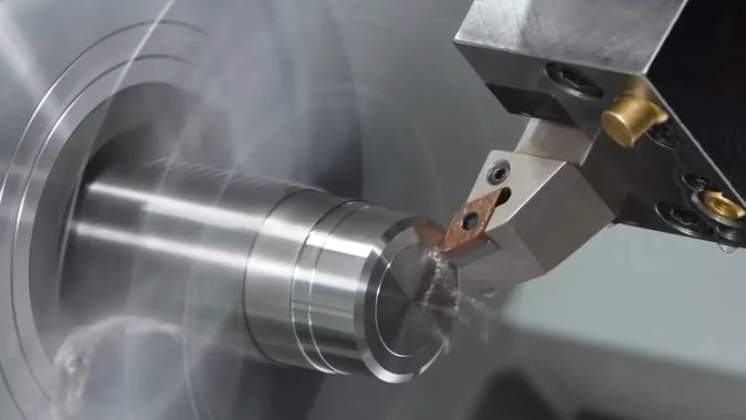
A thin final pass may remove the intended dimension without producing a clean surface everywhere. The edge can cut near the rim and struggle as conditions change toward the axis. A useful starting point is the relationship between shrinking cutting diameter and the spindle speed available to keep the material moving past the tool.
Why Does Cutting Speed Fall Near the Center Even with Constant Surface Speed Active?
Constant surface speed can improve finish across a face1, but its compensation ends at the RPM ceiling. A light finishing cut can become less stable beyond that point.
Constant surface speed requires increasing rpm as cutting diameter decreases. Once the spindle reaches its permitted limit, cutting speed falls with diameter. At the exact rotational axis, surface speed is zero at any finite rpm. A thin cut and unsuitable edge preparation can worsen the resulting low-speed finish.

The RPM limit changes the cutting conditions
The metric relationship is:
Vc is cutting speed in m/min. D is the current cutting diameter in millimeters. n is spindle speed in rev/min.
Constant surface speed, commonly selected with G96, increases n as D decreases. The control can maintain the requested speed only within the available spindle range.
| Region or condition | Spindle response | Effect on cutting conditions |
|---|---|---|
| CSS below the RPM ceiling | Rpm rises toward the center | Cutting speed stays near the command |
| CSS at the RPM ceiling | Rpm remains capped | Cutting speed decreases with diameter |
| Very small cutting diameter | Available rpm remains finite | Low-speed adhesion and rubbing may become more significant |
| Exact rotational axis | Further acceleration cannot solve the geometry | Rotational surface speed is zero |
A light pass must still form a chip
A small finishing allowance is useful only if the selected edge can remove it cleanly. A heavily honed roughing edge may push or rub thin material instead of forming a stable chip3.
The required allowance depends on material, feed, edge preparation, and the surface left by roughing. A universal minimum such as 0.3 mm cannot describe every finishing setup4.
The tool nose radius and cutting-edge hone radius are different features5. The nose radius shapes the overall tip. The hone is the much smaller rounding at the cutting edge. Both affect light cutting, but they should not be treated as the same dimension.
How Can You Check Whether the Rough Area Begins Where the Spindle Reaches Its RPM Limit?
A roughness boundary can suggest a speed-related problem, but uneven finishing stock can create a similar pattern. The comparison needs actual rpm and allowance measurements.
The check compares the rough-area boundary with Dcap = 1000 × Vc / (π × ncap), the diameter where the commanded CSS reaches the RPM cap. Actual spindle speed and local finishing stock must also be checked. Similar boundaries support the diagnosis but do not establish the cause alone.

The calculation predicts where speed compensation ends
An illustrative example uses a CSS command of 180 m/min and an effective cap of 3000 rev/min:
Dcap = 1000 × 180 / (π × 3000) ≈ 19.1 mm
Below that cutting diameter, the spindle cannot maintain 180 m/min. At 10 mm diameter and 3000 rev/min, cutting speed is approximately 94.2 m/min.
These values demonstrate the calculation and are not recommended settings for a specific machine or workpiece.
| Evidence to collect | What it helps establish |
|---|---|
| Active CSS command and effective RPM cap | Predicted limit diameter |
| Actual rpm against cutting diameter | Where spindle acceleration stops or lags |
| Roughness-boundary radius or diameter | Location of the surface change |
| Remaining axial stock across the face | Whether the finishing cut remains engaged |
| Insert condition and feed mode | Other causes of rubbing or tearing |
The finishing allowance needs a local check
The operator should measure remaining axial stock relative to the final face datum at a planned stop before finishing. A measurement near the outside alone cannot establish the allowance across the whole face.
Roughing waviness, elastic recovery, or workpiece distortion can leave a nominal finishing pass with very little stock in some areas6. Those areas may be rubbed instead of fully recut.
A measured boundary radius must be doubled before comparison with Dcap. The machine’s X display also needs interpretation as a radius or diameter value.
A controlled trial can change the CSS command within the tool’s recommended range and retain the same RPM cap. Feed per revolution, actual stock, and tool condition should remain comparable.
A shifted roughness boundary provides supporting evidence. Surface deterioration may still begin farther inside the speed-limit diameter because the material and edge tolerate some speed reduction.
How Does Feed per Revolution Differ from Feed per Minute During Facing?
Reducing feed may appear to improve a finishing pass, but excessive reduction can promote rubbing. The active feed mode determines what happens as rpm rises.
Feed per revolution maintains the programmed tool advance for each spindle turn. Feed per minute maintains travel speed, so advance per revolution decreases as rpm increases. During light finishing, that decrease can produce chips too thin for the cutting edge. Neither feed mode is inherently more accurate.
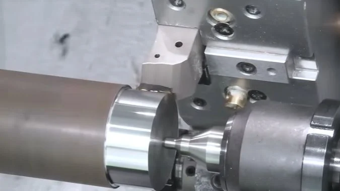
The same travel speed can produce different feed per revolution
The feed relationship is:
F is travel feed in mm/min. f is feed per revolution in mm/rev. n is spindle speed in rev/min.
The following arithmetic example shows how the two commands behave.
| Feed command | At 1000 rev/min | At 3000 rev/min |
|---|---|---|
| 0.10 mm/rev | 100 mm/min travel | 300 mm/min travel |
| 100 mm/min | 0.10 mm/rev | Approximately 0.033 mm/rev |
With fixed feed per minute, the tool advances less per revolution as CSS raises rpm. Finer geometric feed marks may result, but an unsuitable edge can also start rubbing.
Feed per revolution keeps the tool advance consistent during the speed increase. It does not correct insufficient allowance or restore a damaged edge.
Feed and edge preparation must work together
A sharp finishing geometry can form thin chips with lower forces than an edge designed for heavy cutting. A controlled small hone can still provide useful edge strength. Heavier honing is not automatically suitable for a very light pass.
The chip thickness depends on feed and local cutting geometry as well as depth of cut8. Nominal allowance alone cannot establish whether the edge will cut cleanly.
A larger nose radius can reduce theoretical feed-mark height9, but it can also increase forces and vibration in a flexible setup. The selection should balance finish requirements with available rigidity.
Under constant radial feed per revolution, spiral spacing remains approximately constant. A dull or smeared surface with fine marks needs inspection for rubbing, adhesion, and wear. Further feed reduction should follow that evidence.
How Should Surface Finish Be Compared at the Outer Diameter, Mid-Radius, and Center?
Surface brightness alone cannot distinguish low-speed tearing, rubbing, and tool wear. A recorded comparison across the face helps connect the defect with the cutting conditions.
Surface finish should be compared at defined radial positions using consistent lighting and measurement settings. The record should include cutting diameter, actual rpm, feed per revolution, and local allowance. Tool inspection then helps distinguish adhered material from wear. A central nub also requires a tool-height and toolpath check.
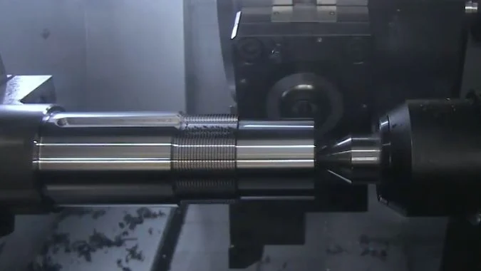
The three regions need comparable records
The outer measurement should avoid an edge chamfer or burr. Mid-radius lies halfway between the axis and the outer edge. A central measurement needs a stated radius because a roughness trace cannot represent a mathematical point.
| Region | Surface evidence to record | Related checks |
|---|---|---|
| Near the outer diameter | Baseline feed marks, tearing, or smearing | Edge condition and actual finishing stock |
| Mid-radius | Whether defects begin or remain unchanged | CSS response, feed mode, and stock variation |
| Near the center | Rough patches, burnishing, or waviness | Low cutting speed, thin-chip cutting, and tool height |
| Exact center | Raised nub or remaining material | Center-height setting and programmed end position |
The finish does not have to worsen steadily from rim to center. Similar poor finish across all three regions points toward a broader problem with allowance, edge selection, wear, or stability.
Tool inspection separates deposits from material loss
Built-up edge is adhered workpiece material near the cutting edge10. Its formation and detachment can leave intermittent torn patches and change the effective cutting geometry.
Flank wear is loss of tool material behind the edge11. A growing wear land can contribute to rubbing, but rubbing can also occur with a fresh edge when chip thickness is too small.
The stopped tool should be inspected under magnification before its condition is altered. Deposits, missing carbide, and wear may coexist. Surface patches or noise alone cannot establish which mechanism dominates.
A suitable finishing geometry and consistent lubricant delivery can help adhesion-prone materials. Wear replacement limits should follow the insert and part requirements.
Comparative trials should preserve the useful evidence
A trial should change one factor and repeat the same inspection positions. A feed-direction comparison also needs a holder and insert suitable for the proposed path; outward finishing is not a universal cure.
Remaining vibration calls for checks of overhang, clamping distortion, and machine condition. Suspected axial spindle movement needs a specified service check.
Roughness measurements should use consistent trace direction and evaluation settings. A central area too small for the normal trace needs a separate local assessment.
Conclusion
A rough center needs checks of actual cutting speed, local allowance, feed mode, and edge condition. Controlled comparisons help identify whether speed loss, rubbing, adhesion, or wear dominates.
-
"When you’re facing on a CNC lathe, do you use constant …", https://www.facebook.com/GCodeTutor/posts/when-youre-facing-on-a-cnc-lathe-do-you-use-constant-surface-speed-g96-or-stick-/1225833936255283/. Constant surface speed control has been documented to reduce surface finish variation across face cuts by maintaining more consistent cutting conditions as diameter changes, though benefits depend on material and tooling selection. Evidence role: general_support; source type: research. Supports: CSS mode can improve surface finish consistency across varying diameters in turning operations. Scope note: The cited research may address turning operations generally rather than specifically comparing finish quality at different radial positions during facing ↩
-
"Turning Equations", https://www.montana.edu/jdavis/met314/documents/homework/Turning%20Examples.pdf. The cutting speed formula Vc = π × D × n / 1000 is the standard relationship used in machining, where Vc is cutting speed in meters per minute, D is diameter in millimeters, and n is rotational speed in revolutions per minute, with the factor 1000 converting millimeters to meters. Evidence role: mechanism; source type: education. Supports: This formula represents the standard calculation for cutting speed in metric units. ↩
-
"Estimation of Minimum Uncut Chip Thickness during Precision …", https://pmc.ncbi.nlm.nih.gov/articles/PMC8745993/. Research on minimum chip thickness demonstrates that when depth of cut approaches the edge hone radius, the cutting mechanism transitions from shearing to plowing, with increased rubbing and surface deterioration rather than clean chip formation. Evidence role: mechanism; source type: research. Supports: Edge hone radius affects minimum chip thickness and cutting behavior in light passes. Scope note: Studies typically focus on specific tool-material combinations and may not quantify the exact hone radius threshold for all finishing scenarios ↩
-
"Machining Allowance", https://www.3erp.com/blog/machining-allowance/. Machining literature indicates that appropriate finishing allowance depends on workpiece material properties, tool geometry and condition, machine rigidity, surface finish requirements, and the condition of the previously machined surface, with recommended values varying significantly across different applications. Evidence role: general_support; source type: research. Supports: Finishing allowance requirements vary with multiple machining parameters. Scope note: Sources may provide ranges or guidelines for specific material-tool combinations rather than explicitly stating that universal values are inadequate ↩
-
"Getting a Better Edge: Design & Engineering", https://ctemag.com/articles/getting-better-edge/. Cutting tool standards distinguish between nose radius (the larger radius forming the tool tip profile, typically 0.4–1.6 mm) and edge hone or edge preparation (the micro-geometry at the cutting edge itself, typically 10–50 μm), which serve different functional purposes in the cutting process. Evidence role: definition; source type: institution. Supports: Nose radius and edge hone are distinct geometric parameters in cutting tool design. ↩
-
"Skewness", https://en.wikipedia.org/wiki/Skewness. Research on machining accuracy demonstrates that elastic recovery (springback) of the workpiece after roughing operations and thermal or mechanical distortion during machining can result in non-uniform stock distribution, causing the actual depth of cut in finishing passes to vary across the workpiece surface. Evidence role: mechanism; source type: research. Supports: Elastic recovery and distortion affect actual material removal in finishing. Scope note: Studies may focus on specific materials or geometries and may not quantify the magnitude of variation for all finishing scenarios ↩
-
"Speeds and Feeds", https://web.mae.ufl.edu/designlab/Advanced%20Manufacturing/Speeds%20and%20Feeds/Speeds%20and%20Feeds.htm. The feed rate relationship F = f × n is fundamental to machining calculations, where F represents feed rate in distance per unit time (mm/min), f is feed per revolution (mm/rev), and n is spindle speed (rev/min), allowing conversion between feed per revolution and feed per minute modes. Evidence role: mechanism; source type: education. Supports: This formula defines the relationship between feed modes in machining. ↩
-
"Estimation of Minimum Uncut Chip Thickness during Precision …", https://pmc.ncbi.nlm.nih.gov/articles/PMC8745993/. Metal cutting theory establishes that undeformed chip thickness is primarily determined by feed rate and tool entering angle in turning operations, while also being influenced by depth of cut, nose radius, and local cutting edge geometry, with these parameters combining to define the cross-sectional area of material removed per cutting edge pass. Evidence role: mechanism; source type: education. Supports: Chip thickness results from the interaction of multiple cutting parameters. Scope note: Theoretical models may simplify the complex three-dimensional geometry of actual chip formation, particularly near the tool nose radius ↩
-
"Surface Finish Calculator (Ra from Feed & Nose Radius)", https://snubber.ai/calculators/surface-finish-calculator. The theoretical surface roughness in turning operations is geometrically related to feed rate and nose radius through the formula Rt ≈ f²/(8×r), where larger nose radius reduces the calculated peak-to-valley height of feed marks for a given feed per revolution. Evidence role: mechanism; source type: education. Supports: Nose radius affects theoretical surface roughness through geometric relationships. Scope note: This represents ideal geometric conditions and does not account for tool wear, vibration, material properties, or other practical factors that affect actual surface finish ↩
-
"Built-up edge", https://en.wikipedia.org/wiki/Built-up_edge. Built-up edge is defined as a layer of workpiece material that adheres to the rake face of the cutting tool under certain cutting conditions, typically at low to moderate cutting speeds, forming through pressure welding and plastic deformation of the workpiece material. Evidence role: definition; source type: encyclopedia. Supports: Built-up edge is a recognized machining phenomenon involving workpiece material adhesion. ↩
-
"Flank Wear Estimation Under Varying Cutting Conditions", http://www-personal.umich.edu/~ykoren/uploads/Flank_wear_estimation_under_varying_cutting_conditions.pdf. Flank wear is defined in tool life standards as the gradual loss of tool material on the flank (clearance) face, typically measured as the width of the wear land perpendicular to the cutting edge, and is one of the primary tool wear mechanisms in metal cutting. Evidence role: definition; source type: institution. Supports: Flank wear is a standard tool wear classification. ↩

Chris Lu
Leveraging over a decade of hands-on experience in the machine tool industry, particularly with CNC machines, I'm here to help. Whether you have questions sparked by this post, need guidance on selecting the right equipment (CNC or conventional), are exploring custom machine solutions, or are ready to discuss a purchase, don't hesitate to CONTACT Me. Let's find the perfect machine tool for your needs.