

Why Does Surface Finish Get Worse Near the Center When Facing on CNC Lathe?
A faced part can look smooth at the rim and rough at the center. Checking cutting speed, feed mode, and tool height helps explain the change.
Surface finish often worsens near the center because cutting speed falls after the spindle reaches its RPM limit. Low speed can promote material adhesion, tearing, and rubbing. Incorrect tool height, unsuitable feed, or a damaged insert can worsen the central area, so the speed limit needs verification.
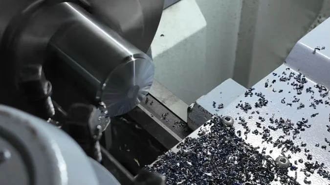
The spindle can sound steady while cutting conditions change across a face. Each revolution carries less material past the tool as the contact diameter shrinks. Constant surface speed control compensates by increasing rpm, but the available speed has a ceiling.1 The important distinction is whether the tool is still within that compensation range.
Why Does Cutting Speed Fall Near the Center Even with Constant Surface Speed Active?
Constant surface speed can improve facing consistency, but roughness may still appear near the axis. The spindle’s available RPM range explains where compensation ends.
Cutting speed falls near the center because constant surface speed requires progressively higher rpm as diameter decreases. The spindle eventually reaches its permitted limit. Rpm then stays capped, and cutting speed decreases with diameter. At the exact axis, rotational surface speed is zero at any finite rpm.
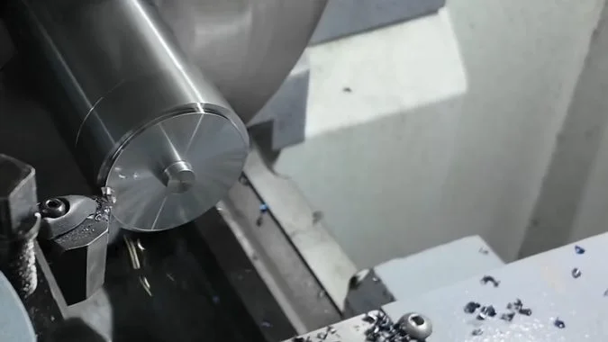
Constant surface speed requires rising rpm
The metric cutting-speed relationship is:
Vc is cutting speed in m/min. D is the current cutting diameter in millimeters. n is spindle speed in rev/min.
The diameter is the location of the cut, rather than the original blank diameter. Constant surface speed control, commonly selected with G963, increases spindle speed as that cutting diameter decreases.
| Operating condition | Spindle behavior toward the center | Cutting-speed behavior |
|---|---|---|
| Fixed-rpm facing | Rpm remains constant | Speed falls with diameter |
| CSS below the RPM limit | Rpm increases | Speed remains near the commanded value |
| CSS at the RPM limit | Rpm stops increasing | Speed falls with diameter |
| Exact rotational axis | Available rpm remains finite | Rotational surface speed is zero |
The cutting edge can leave its effective working range
Lower speed can encourage built-up edge in materials prone to adhesion.4 Material can accumulate on the edge and break away, leaving torn patches or an uneven finish.
Rubbing can also become more significant with a dull edge, unsuitable feed, or very shallow engagement. Low speed does not produce the same result in every material.
CSS can maintain suitable conditions over much of the face, but it cannot maintain a positive surface speed at zero diameter. Tool geometry and accurate center height remain important at the final central region.
How Can You Check Whether the Rough Area Begins Where the Spindle Reaches Its RPM Limit?
A rough central band may coincide with the speed cap, but appearance alone cannot establish the cause. Calculated diameter and actual spindle data provide a comparison.
The check compares the rough area’s boundary with the diameter where CSS requires the permitted maximum rpm. That diameter is Dcap = 1000 × Vc / (π × ncap). Actual rpm should also be recorded. Similar locations support a speed-related explanation, but tool condition and feed still need checking.
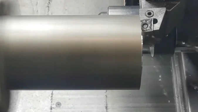
The calculation locates the start of speed loss
The calculation uses the programmed CSS value and the effective RPM cap. A program limit, spindle range, or machine setting may determine the available maximum.
An illustrative example uses Vc = 180 m/min and ncap = 3000 rev/min:
Dcap = 1000 × 180 / (π × 3000) ≈ 19.1 mm
The calculation predicts that CSS can maintain 180 m/min down to approximately 19.1 mm diameter. At 10 mm diameter and the same capped rpm, cutting speed is approximately 94.2 m/min.
These figures illustrate the calculation and do not specify settings for a particular setup.
| Evidence to record | Purpose |
|---|---|
| Active speed mode and CSS command | Confirms what the control is requesting |
| Effective RPM limit | Establishes the calculation’s speed ceiling |
| Actual rpm against cutting diameter | Confirms where acceleration stops |
| Diameter of the rough-area boundary | Links the visible change to cutting position |
| Feed, insert condition, and finishing allowance | Checks other influences on the comparison |
The boundary needs a measured interpretation
The inspector can locate the roughness boundary through optical inspection or a surface trace. A measured radius must be doubled before comparison with Dcap. The machine’s X display also needs interpretation as a diameter or radius value.
Surface damage may begin inside the calculated limit diameter, once speed becomes unsuitable for the material. Spindle acceleration limits can also cause actual speed to lag before the cap is reached.
A controlled trial can use a different supplier-approved CSS command with the same RPM cap. The predicted transition diameter changes, but the comparison needs consistent feed per revolution, material, allowance, and tool condition.
Any review of the cap must respect the permitted speed of the machine, chuck, jaws, and workpiece setup.
How Does Feed per Revolution Differ from Feed per Minute During Facing?
Changing rpm can change the tool advance per spindle turn. Checking the active feed mode helps explain differences in texture across the faced surface.
Feed per revolution keeps tool advance per spindle turn at the programmed value. Feed per minute keeps travel speed fixed, so advance per revolution falls as rpm rises. Neither mode is inherently more accurate. Feed per revolution often provides a more consistent feed relationship during CSS facing.
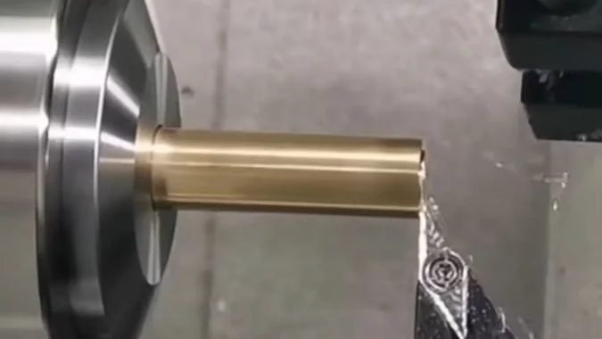
The feed relationship changes with spindle speed
The relationship is:
F is feed in mm/min. f is feed in mm/rev. n is spindle speed in rev/min.
Feed per revolution remains a useful definition during changing rpm. The control changes travel speed to maintain the programmed advance for each spindle turn.
The following arithmetic example compares two unchanged feed commands.
| Feed command | At 1000 rev/min | At 3000 rev/min |
|---|---|---|
| 0.10 mm/rev | 100 mm/min travel | 300 mm/min travel |
| 100 mm/min | 0.10 mm/rev | Approximately 0.033 mm/rev |
With constant feed per minute, increasing rpm produces smaller advance per revolution. The geometric feed marks may become finer, but an excessively small chip thickness can also encourage rubbing6.
Once rpm reaches its cap, both unchanged feed commands produce a constant advance per revolution. Cutting speed still falls as diameter decreases.
Spiral spacing and finish need separate interpretation
Under constant radial feed per revolution, the spiral’s radial spacing stays approximately constant. The shrinking circumference alone does not make that spacing progressively tighter.
Feed per revolution controls this relationship; it does not guarantee a particular finish. Edge geometry, nose radius, vibration, and material adhesion also affect the surface.
A moderate feed reduction can reduce geometric feed marks, but the trial should remain within the insert’s effective cutting range. A larger nose radius can improve the theoretical profile but may increase forces and vibration.7
The program review should confirm the feed units and the control-specific mode. The same numerical F value can represent very different tool movements in the two modes.
How Should Surface Finish Be Compared at the Outer Diameter, Mid-Radius, and Center?
A shiny rim and dull center provide a clue, but lighting can exaggerate differences. Consistent inspection across defined locations helps identify the actual pattern.
Surface finish should be compared at recorded radii using consistent lighting, measurement direction, and instrument settings. Each location should also have its cutting diameter, actual rpm, and feed recorded. A central nub needs separate inspection because tool-height or toolpath errors can coexist with speed-related roughness.

The comparison needs defined locations
The inspector should record the outer diameter and select repeatable radial positions. Mid-radius means halfway between the rotational axis and the outside edge. Its cutting diameter is half the part’s outside diameter.8
The outer measurement should avoid an edge chamfer or burr. The central measurement should identify the actual radius because a roughness trace cannot represent a mathematical point.
| Inspection area | Useful observations | Matching process information |
|---|---|---|
| Near the outer diameter | Baseline texture, tearing, or feed marks | CSS status, actual rpm, and feed |
| Mid-radius | Whether finish remains consistent or begins changing | Cutting diameter relative to Dcap |
| Near the center | Smearing, rough patches, or larger undulations | Capped rpm, low cutting speed, and tool condition |
| Exact center feature | Raised nub, residual material, or a local defect | Tool height and programmed end position |
The observed pattern should guide the next check
The outer diameter does not always have the best finish. Effective CSS and suitable feed can produce similar results at the outer and middle regions. Poor finish across the whole face calls for a broader check of the insert, workholding, coolant delivery, and cutting data.
A rough central region beginning after the actual RPM plateau supports investigation of low-speed cutting conditions. A small isolated nub calls for a direct check of tool center height and the facing path.
Roughness comparisons should use consistent trace direction relative to the surface lay and the same evaluation settings.9 A central area too small for that trace needs a separate local assessment.
Visual brightness, measured roughness, and face flatness describe different features. A polished-looking patch can still contain smearing or an unacceptable local profile.
Conclusion
Center finish improves through verified CSS limits, suitable feed per revolution, correct tool height, and consistent inspection across the face. Actual speed data helps identify the dominant cause.
-
"When you’re facing on a CNC lathe, do you use constant …", https://www.facebook.com/GCodeTutor/posts/when-youre-facing-on-a-cnc-lathe-do-you-use-constant-surface-speed-g96-or-stick-/1225833936255283/. CNC turning systems using constant surface speed mode automatically increase spindle RPM as cutting diameter decreases to maintain programmed surface velocity, subject to machine-specific maximum RPM constraints. Evidence role: mechanism; source type: education. Supports: how constant surface speed control adjusts spindle RPM inversely with cutting diameter. ↩
-
"Speeds and feeds", https://en.wikipedia.org/wiki/Speeds_and_feeds. The relationship between cutting speed (Vc in m/min), workpiece diameter (D in mm), and spindle speed (n in rev/min) is expressed as Vc = πDn/1000, derived from the circumference formula with unit conversion. Evidence role: definition; source type: education. Supports: the standard formula relating cutting speed, diameter, and spindle speed in metric units. ↩
-
"G96 and G97 spindle speed control", https://gcodetutor.com/cnc-machine-training/g96-g97-spindle-speed.html. In CNC lathe programming following ISO 6983 and similar standards, G96 activates constant surface speed mode, while G97 returns to constant RPM mode. Evidence role: definition; source type: education. Supports: the standard G-code designation for constant surface speed mode. Scope note: Some machine tool builders may use proprietary variations of standard G-codes ↩
-
"Built-up edge", https://en.wikipedia.org/wiki/Built-up_edge. Machining research identifies built-up edge as a phenomenon occurring predominantly at low to moderate cutting speeds where temperature and pressure conditions favor material welding to the tool rake face, with severity varying by workpiece material ductility. Evidence role: mechanism; source type: research. Supports: the relationship between cutting speed and built-up edge formation. Scope note: The critical speed range for BUE formation is material-specific and also depends on tool coating and coolant conditions ↩
-
"Speeds and feeds", https://en.wikipedia.org/wiki/Speeds_and_feeds. The feed rate (F in mm/min) equals the product of feed per revolution (f in mm/rev) and spindle speed (n in rev/min), a fundamental relationship in machining kinematics. Evidence role: definition; source type: education. Supports: the mathematical relationship between feed rate, feed per revolution, and spindle speed. ↩
-
"Estimation of Minimum Uncut Chip Thickness during Precision …", https://pmc.ncbi.nlm.nih.gov/articles/PMC8745993/. Metal cutting research establishes that when uncut chip thickness approaches the cutting edge radius, the material undergoes elastic-plastic deformation and rubbing rather than shearing, reducing cutting efficiency and surface quality. Evidence role: mechanism; source type: research. Supports: the phenomenon of rubbing or ploughing when chip thickness falls below a critical minimum. Scope note: The critical minimum chip thickness varies with tool edge preparation and workpiece material properties ↩
-
"An Investigation of Cutting Tool Chatter Vibration in Machine …", https://scholarworks.uni.edu/cgi/viewcontent.cgi?article=4664&context=grp. Machining studies demonstrate that increased nose radius reduces theoretical surface roughness through improved geometric profile generation, but simultaneously increases radial cutting forces and susceptibility to chatter vibration, particularly in less rigid setups. Evidence role: general_support; source type: research. Supports: the relationship between tool nose radius, theoretical surface finish, cutting forces, and vibration tendency. Scope note: The optimal nose radius depends on workpiece rigidity, machine stiffness, and required surface finish ↩
-
"Radius, diameter, & circumference | Circles (article)", https://www.khanacademy.org/math/get-ready-for-geometry/x8a652ce72bd83eb2:get-ready-for-circles-and-solid-geometry/x8a652ce72bd83eb2:area-and-circumference-of-circles/a/radius-diameter-circumference. In circular geometry, diameter equals twice the radius; therefore, a position at half the maximum radius corresponds to a cutting diameter equal to half the part’s outside diameter. Evidence role: definition; source type: encyclopedia. Supports: the relationship between radius and diameter in circular geometry. ↩
-
"Surface Texture", https://www.nist.gov/document/asm-hb18pdf. Surface texture measurement standards specify that roughness evaluations should maintain consistent trace direction relative to the surface lay and use identical filter settings and evaluation lengths to ensure comparable results. Evidence role: general_support; source type: institution. Supports: the importance of consistent measurement direction and settings in surface roughness evaluation. Scope note: Specific requirements vary between ISO, ASME, and other national standards ↩

Chris Lu
Leveraging over a decade of hands-on experience in the machine tool industry, particularly with CNC machines, I'm here to help. Whether you have questions sparked by this post, need guidance on selecting the right equipment (CNC or conventional), are exploring custom machine solutions, or are ready to discuss a purchase, don't hesitate to CONTACT Me. Let's find the perfect machine tool for your needs.