

كيفية تحديد قطر الظرف مقابل الحد الأقصى لسرعة دوران المغزل في مخرطة CNC؟
قد تدرج كتيبات المخرطة سرعة 5000 دورة في الدقيقة، ولكن غالبًا لا يمكن لظرف التثبيت الكبير العمل بهذه السرعة. يجب تحديد قطر الظرف وسرعة دوران عمود الدوران (RPM) معاً، مع مراعاة هامش أمان.
يتم تحديد قطر الظرف في مخرطة CNC بناءً على القيمة الأقل بين سرعة دوران عمود الدوران المحددة على لوحة البيانات والسرعة الآمنة المقدرة للظرف. يجب أن يكون حد الظرف أعلى من الحد الأقصى لعمود الدوران مع وجود هامش أمان، ويتم اختيار الحجم بناءً على قطعة العمل وليس على أكبر حجم متاح في الكتالوج.
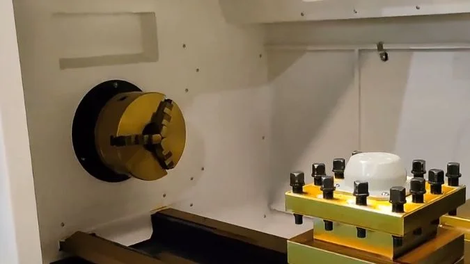
قد تشير لوحة البيانات إلى 5000 دورة في الدقيقة، ولكن قد لا تكون هذه هي السرعة المناسبة للعمل، حيث أن للظرف حدوده الخاصة. تؤدي القوة الطاردة المركزية على فكوك التثبيت إلى تقليل قوة الإمساك مع ارتفاع سرعة الدوران.1. تستخدم الورشة القيمة الأقل من بين هذين الحدين، وهما سرعة لوحة بيانات عمود الدوران والسرعة الآمنة المقدرة للظرف.
ما الفرق بين سرعة دوران عمود الدوران المحددة على لوحة البيانات والسرعة الآمنة المقدرة للظرف؟
تستخدم الورش السرعة القصوى لعمود الدوران كحد أقصى للظرف، وهو ما قد يكون غير آمن عند تلك السرعة، لذا يجب مقارنة لوحتي البيانات.
سرعة لوحة بيانات عمود الدوران هي السرعة التي يمكن أن يدور بها عمود الدوران أو المحرك، بينما السرعة الآمنة المقدرة للظرف هي السرعة التي يمكن للظرف الدوران بها مع الحفاظ على إمساك آمن. هذان الحدان ليسا متطابقين، والقيمة الأقل منهما هي التي تعتمدها الورشة.
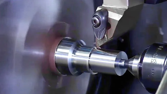
ما تشير إليه لوحة بيانات عمود الدوران
سرعة لوحة بيانات عمود الدوران هي السرعة التي يسمح بها تصميم عمود الدوران. تتحدد هذه السرعة بناءً على المحامل، والتشحيم، وقوة المحرك، وهيكل الآلة.2. توضح اللوحة عادةً السرعة المقدرة والسرعة القصوى. السرعة المقدرة هي نقطة العمل المستقرة، بينما السرعة القصوى هي حد التصميم، وتجاوزها يؤدي إلى تلف عمود الدوران. هذا الرقم يتعلق بالمحرك والمحامل، وليس بقوة الإمساك.
ما تشير إليه السرعة الآمنة المقدرة للظرف
يحدد مصنع الظرف السرعة القصوى المسموح بها بناءً على الهيكل، وقوة التثبيت، والقوة الطاردة المركزية. بعد تجاوز هذه السرعة، تندفع الفكوك للخارج وتقل قوة الإمساك، مما قد يؤدي إلى خروج قطعة العمل من الظرف. يتحدد هذا الحد بناءً على القطر، ووزن الفكوك، وقوة التثبيت، والتوازن. تدرج إحدى عائلات منتجات Kitagawa سرعات 7000، 6000، 4500، و3600 دورة في الدقيقة لمختلف الأحجام.3. يعتبر منحنى السرعة مقابل قوة التثبيت الخاص بالمورد هو المرجع للتحقق. يجب أن يكون حد الظرف أعلى من الحد الأقصى لعمود الدوران مع وجود هامش أمان.
لماذا لا يمكن تبادل هذين الحدين؟
يمكن للمغزل الدوران بسرعة تفوق قدرة الظرف على حمل القطعة. كما يمكن تصنيف الظرف لسرعة أعلى من قدرة المغزل المتواضعة. يظل الاستخدام اليومي خاضعاً للسرعة الأدنى. إن الخلط بين هذين المعيارين في عرض السعر يخفي القدرة الحقيقية. فالورشة التي تلاحق رقم سرعة المغزل فقط ستجد في النهاية لوحة الظرف ملقاة على الأرض.
| الساعة | ما تقيسه | ما يحدده | ما يحدث بعد تجاوزه |
|---|---|---|---|
| سرعة دوران المغزل المقدرة (RPM) | مدى سرعة دوران المغزل | المحامل، التشحيم، المحرك، الهيكل | تلف المغزل |
| السرعة الآمنة المقدرة للظرف | مدى سرعة دوران الظرف مع قبضة آمنة | القطر، الفكوك، القوة، التوازن | ضعف القبضة، خطر تطاير القطعة |
| قدرة الورشة | القيمة الأدنى بين الاثنين | كلا اللوحتين، بالإضافة إلى هامش أمان | يجب ألا تتجاوز المهمة هذه القيمة |
لماذا يؤدي الظرف الأكبر إلى خفض سرعة الدوران القابلة للاستخدام حتى لو كان عمود الدوران قادراً على الدوران بشكل أسرع؟
يبدو الجسم الأكبر وكأنه يوفر قبضة أقوى. ولكن عند السرعات العالية، فإنه يدفع كتلة أكبر نحو الخارج، مما يقلل من سرعة الدوران القابلة للاستخدام حتى لو كان المغزل قادراً على سرعات أعلى.
يؤدي الظرف الأكبر حجماً إلى خفض سرعة الدوران القابلة للاستخدام لأن السرعة المحيطية وقوة الطرد المركزي للفكوك تزداد مع القطر. تتضاءل قوة التثبيت، ويزداد الاهتزاز، وتصبح السرعة الآمنة أقل من السرعة الفائقة للمغزل. الحجم الأكبر ليس هو الخيار الافتراضي دائماً.

السرعة الخطية ورمي القطع
عند نفس عدد الدورات في الدقيقة، يكون للظرف الأكبر سرعة محيطية أعلى4. يتعرض جسم الظرف والفكوك بعد ذلك لارتفاع حاد في القوة الطاردة المركزية. قد يضعف التثبيت، مما يؤدي إلى خروج القطعة من الفكوك. مع ارتفاع عدد الدورات، تندفع الفكوك للخارج وتنخفض قوة التثبيت. يؤدي استخدام ظرف أكبر وفكوك أثقل إلى تفاقم هذا الاندفاع. قد تتحرك القطعة أثناء القطع. لذا، يتطلب القطع الثقيل قوة تثبيت متبقية عند السرعة القصوى، وليس فقط القوة الاستاتيكية المذكورة في الكتالوج.
الصلابة والتوازن
الظرف الكبير عبارة عن كتلة ضخمة، ويجب أن تتحمله عمود الدوران والشفة. يؤدي الدعم الضعيف عند السرعات العالية إلى بدء الاهتزاز وترك علامات على السطح. يعد التوازن الديناميكي أيضاً أكثر صعوبة في الأجسام الكبيرة5. عدم التوازن عند السرعة يزيد من الضوضاء والاهتزاز6. وبالتالي تنخفض السرعة القابلة للاستخدام (RPM) للحفاظ على هدوء المجموعة، حتى لو كان محرك عمود الدوران لا يزال يمتلك سرعة غير مستغلة.
مطابقة الجسم مع القطعة
يتم تحديد القطر الاسمي للظرف بناءً على نطاق قطعة العمل ورأس عمود الدوران. الحجم الأكبر ليس هو الخيار الافتراضي دائماً. يجب أن يتجاوز الحد الأقصى للتثبيت الخارجي القطر الخارجي للقطعة بهامش كافٍ. تفقد الفكوك قوتها عند السن الأخير، كما يتطلب التثبيت الداخلي شوطاً كافياً للفكوك. يجب أن تتطابق الشفة مع رأس عمود الدوران، وإلا لن يتم تركيب الظرف. غالباً ما تستخدم مخارط CNC الأفقية أجساماً بأقطار تتراوح بين 100 و500 مم. تشمل الأحجام الشائعة 160، 260، 400، و500 مم.7. يمكن للمخارط الرأسية أن تتجاوز 500 مم8. تتطلب الأقراص الكبيرة سرعة منخفضة وعزم دوران مرتفعاً. وتتطلب الأعمدة الصغيرة نطاقاً مستقراً وعالي السرعة.
| المشغل | ما يفعله ظرف أكبر | التأثير على عدد الدورات في الدقيقة القابل للاستخدام |
|---|---|---|
| سرعة الحافة | أعلى عند نفس عدد الدورات في الدقيقة | انخفاض الحد الأقصى الآمن |
| اندفاع الفك | كتلة أكبر تُدفع للخارج | تتراجع قوة الإمساك في وقت أبكر |
| الكتلة على رأس المخرطة | ضغط أكبر على عمود الدوران والحافة | الاهتزاز عند السرعة |
| التوازن | أكثر صعوبة في الحفاظ على استوائه | ارتفاع الضوضاء والاهتزاز |
| ملاءمة القطعة | مطلوب فقط عندما يتطلب القطر الخارجي ذلك | القطر الإضافي يمثل خطراً غير مستغل |
كيف يجب احتساب كتلة الفكوك والأثقال الموازنة ضمن تصنيف سرعة الظرف؟
A speed chart that ignores jaw mass is a paper limit. Heavy jaws and a wide grip then eat the force the nameplate still claims.
Jaw mass inside the chuck speed rating includes the base jaw, top jaw, and moving hardware. Heavier jaws and a larger center-of-gravity radius raise centrifugal force with the square of RPM. Counterweights can offset that throw.
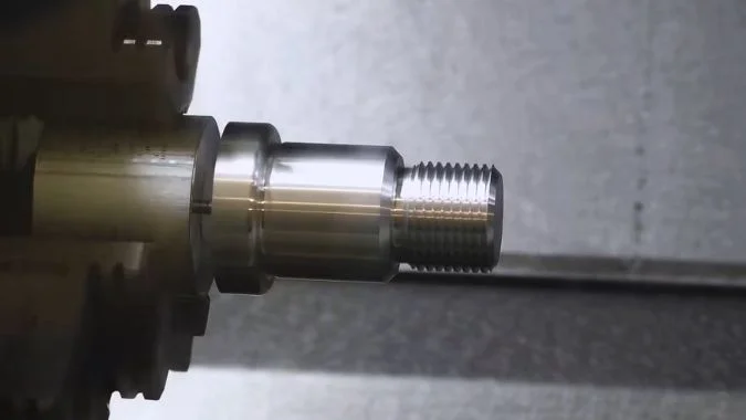
Count the moving mass
The core check is how jaw centrifugal force offsets clamping force. Force rises with the square of speed9. Effective grip then falls. A workpiece can fly, or a jaw can fail. Heavier jaws raise centrifugal force at the same RPM, so grip loss is worse. The counted mass is one jaw: base jaw, top jaw, and connecting parts. A booster screw structure must count the whole moving mass.
Counterweights and center of gravity
Some chucks add centrifugal compensation. A reverse mechanism fights the outward throw and holds grip at higher speed. That option is part of the speed rating, not a shop add-on after the quote. Jaw center-of-gravity radius also matters. A jaw sitting farther out raises centrifugal force. Large-diameter work moves that radius out, so rated speed should fall. A wide grip on a large disk is then a lower RPM job, even on the same chuck body.
How makers set the number
Chuck makers often set maximum speed at the point where centrifugal force reaches two-thirds of maximum clamping force10. Weak points still need a strength check at that speed. Jaw-seat keys, bolts, and screws take shear and torsion. Thin keys, few bolts, or a low bolt grade fail first. Workpiece weight, center of gravity, a tailstock or steady rest, and cutting force then change the real safe speed. A safety factor belongs on the shop number. The chuck’s own plate is not the last word.
| Item to count | Why it changes the rating |
|---|---|
| Base jaw + top jaw + hardware | Moving mass sets centrifugal force |
| Booster-screw moving parts | Extra mass still throws outward |
| Center-of-gravity radius | A wider grip raises force at the same RPM |
| Counterweight / compensation | تتسبب الإزاحات في الرمي ويمكنها الحفاظ على قوة الإمساك عند سرعات أعلى |
| قاعدة قوة التثبيت بنسبة 2/3 | التعريف الشائع للسرعة القصوى لدى المصنعين |
| المفاتيح، والمسامير، والبراغي | الحد الأدنى للقوة عند تلك السرعة |
| وزن القطعة، والراحة، وقوة القطع | عامل الأمان الخاص بالورشة بالإضافة إلى لوحة البيانات |
لماذا قد تظل سرعة الظرف محدودة بقيمة أقل بكثير مما هو مذكور في كتيب “سرعة عمود الدوران 5000 دورة في الدقيقة”؟
في الكتيبات، تعتبر 5000 دورة في الدقيقة الحد الأقصى لعمود الدوران نفسه، بينما تكون لوحة ظرف التثبيت على الجسم غالباً أقل بكثير، وهي التي تحدد القيد.
يظل عمود الدوران المذكور في الكتيب بـ 5000 دورة في الدقيقة مقيداً بسرعة ظرف أقل، لأن الظرف وتركيبة التثبيت يضعان حداً جديداً. فلوحة اسم الظرف، ونوع الفك، والتوازن، ومعيار G50، وعزم الدوران المتاح، كلها تقع تحت رقم الـ 5000 المطبوع.

الرقم الموجود في الكتيب يخص عمود الدوران
5000 r/min on a CNC lathe brochure is the spindle’s own limit. In use, the chuck and fixture become the new cap. The two labels are not the same. A 5000 r/min line does not mean a chucked part may run at 5000. The chuck body and the front guard door carry the permissible speed and the permissible clamp pressure. Those are the maker’s safety bounds from strength, jaw type, and balance. The spindle must not pass them.
What else pulls the cap down
Special jaws and non-standard soft steel jaws clamp less efficiently and throw worse, so the allowed speed falls again. A nut that sits outside the chuck rim is a further cut. An unbalanced workpiece at high speed shakes the machine and the grip. Work near the chuck limit needs a balanced part and clamp pressure at the allowed maximum.
G96 constant surface speed11 is a hard program limit. As diameter falls, theoretical RPM soars. G50 must set a spindle max so the machine and the fixture stay inside strength12. G50 S2000 is one such cap. Speed then shall not exceed 2000 r/min.
High RPM also does not mean the cut can be driven. Short torque or power in the used band leaves the spindle spinning without feeding the tool. Faster spindle speed is not always better on that cut. Speed should then fall on purpose. Drive type, bearings, and lubrication already set the spindle max. Brochure values are often an ideal test. Load on the floor takes a discount.
Read the plates before the brochure
The chuck plate and the guard door are the first check. Workpiece weight, balance, and the cutting method then set a safe speed. The brochure figure is not the operating basis.
| Limit | Typical source | What it does to 5000 r/min |
|---|---|---|
| Spindle brochure | Ideal spindle test | Prints 5000 |
| Chuck nameplate | Body and guard door | New, often lower, cap |
| Special / soft jaws | Extra throw, weaker clamp | Cap falls again |
| Unbalanced part | الاهتزاز عند السرعة | Cap must fall |
| G96 without G50 | RPM soars as diameter falls | Program must lock a max |
| Short torque in the band | Motor cannot drive the cut | Speed should fall on purpose |
الخاتمة
Specify chuck diameter only after the chuck speed limit clears the spindle max with a margin. Size then follows the part. The brochure RPM is not the shop cap.
-
"Factors affecting grip force: Anatomy, mechanics, and referent …", https://pmc.ncbi.nlm.nih.gov/articles/PMC4013148/. Engineering mechanics demonstrates that centrifugal force acting on rotating chuck jaws increases with the square of rotational velocity, creating an outward force that opposes the mechanical clamping force and reduces net gripping capacity. Evidence role: mechanism; source type: research. Supports: the inverse relationship between rotational speed and effective clamping force due to centrifugal effects. ↩
-
"Machine Tool Spindle Bearings Types & Selection Guide", https://pibsales.com/tutorials/machine-tool-spindle-bearings-types-selection-guide/?srsltid=AU7gw4Woq0f0qZH3Pq9Ku02G0SH7bVD6ib4qKPdLvf7ktGDbQzJ2yuaX. Machine tool design literature identifies bearing DN values (bearing bore diameter × RPM), lubrication system capacity, motor power curves, and structural dynamics as the principal factors establishing spindle speed envelopes, with each subsystem imposing distinct operational limits. Evidence role: general_support; source type: education. Supports: the primary engineering constraints that determine maximum spindle operating speeds. ↩
-
"Forming Quality Research on the Variable-Diameter Section …", https://pmc.ncbi.nlm.nih.gov/articles/PMC9414841/. Manufacturer specifications across the chuck industry demonstrate that maximum rated speeds decrease with increasing chuck diameter, reflecting the physics of centrifugal forces and the engineering constraints of maintaining safe clamping at higher peripheral velocities. Evidence role: case_reference; source type: other. Supports: the inverse relationship between chuck diameter and rated maximum speed. Scope note: The specific Kitagawa values cited are manufacturer-specific, though the inverse relationship is industry-wide ↩
-
"Tangential speed", https://en.wikipedia.org/wiki/Tangential_speed. Rotational kinematics establishes that tangential (rim) velocity equals the product of angular velocity and radius (v = ωr), meaning that at constant RPM, peripheral speed increases proportionally with diameter. Evidence role: mechanism; source type: encyclopedia. Supports: the linear relationship between rotational radius and tangential velocity at constant angular velocity. ↩
-
"Rotating Machinery Rotor Balancing", https://rotorlab.tamu.edu/me459/Rotor%20Balancing/Rotating_Machinery_Rotor_Balancing.pdf. Rotating machinery engineering demonstrates that balancing precision requirements become more stringent with increasing diameter and mass, as unbalance forces scale with both mass and the square of the radius, making larger components more sensitive to mass distribution asymmetries. Evidence role: general_support; source type: research. Supports: the increased difficulty of achieving dynamic balance in larger rotating components. ↩
-
"Study on the Influence of Unbalanced Phase Difference …", https://www.mdpi.com/1424-8220/25/6/1691. Vibration engineering establishes that unbalanced rotating masses generate periodic forces proportional to the square of rotational speed, producing vibration amplitudes and noise levels that increase dramatically with RPM, potentially causing surface finish degradation and accelerated bearing wear. Evidence role: mechanism; source type: research. Supports: the relationship between rotational imbalance and vibration severity. ↩
-
"Lathe Chucks: Clamp, Center, and Control Your Work", https://www.mscdirect.com/resources/buying-guides/lathe-chucks. Machine tool industry specifications document that horizontal CNC lathes commonly employ chucks ranging from small precision sizes around 100-200mm for bar work to larger capacities of 400-500mm for heavier components, with size selection driven by workpiece dimensions and machine capacity. Evidence role: general_support; source type: institution. Supports: typical chuck size ranges used in horizontal CNC lathe applications. ↩
-
"Lathe Chuck Types, Mounting & 3-Jaw vs 4-Jaw Guide", https://cncwmt.com/qa/everything-you-need-to-know-about-lathe-chuck/. Machine tool industry data indicates that vertical lathes and vertical turning centers commonly accommodate workholding fixtures ranging from 500mm to several meters in diameter, designed for large-diameter, relatively short workpieces such as rings, flanges, and disks. Evidence role: general_support; source type: institution. Supports: the typical chuck size ranges for vertical lathe configurations. ↩
-
"Centrifugal force", https://en.wikipedia.org/wiki/Centrifugal_force. Classical mechanics establishes that centrifugal force is proportional to the square of angular velocity (F = mω²r), meaning that doubling rotational speed quadruples the outward force on rotating components. Evidence role: mechanism; source type: encyclopedia. Supports: the mathematical relationship between rotational speed and centrifugal force. ↩
-
"Safe speeds for large chucks", https://www.practicalmachinist.com/forum/threads/safe-speeds-for-large-chucks.199517/. Manufacturing standards organizations document that chuck speed ratings typically incorporate safety factors where centrifugal forces are limited relative to static clamping capacity, though specific ratios vary by manufacturer and application. Evidence role: expert_consensus; source type: institution. Supports: the industry practice of setting chuck speed ratings based on centrifugal force thresholds. Scope note: The exact two-thirds ratio may be manufacturer-specific rather than a universal standard ↩
-
"G96 G-Code: Constant Surface Speed CNC Programming", https://www.cnccookbook.com/g96-g-code-constant-surface-speed-cnc/. CNC programming standards define G96 as the command that activates constant surface speed mode, automatically adjusting spindle RPM as tool position changes to maintain consistent cutting velocity at the workpiece surface. Evidence role: definition; source type: institution. Supports: the function of G96 in CNC programming standards. ↩
-
"Any tips on calculating G50 and G96 in CNC machining?", https://www.facebook.com/groups/769782850345135/posts/1298664774123604/. CNC programming standards specify that G50 with an S parameter establishes an upper spindle speed limit, preventing the spindle from exceeding a specified RPM regardless of other programmed commands, particularly important when using constant surface speed mode. Evidence role: definition; source type: institution. Supports: the function of G50 in limiting maximum spindle speed. ↩

كريس لو
بالاستفادة من أكثر من عشر سنوات من الخبرة العملية في مجال صناعة أدوات الماكينات، خاصةً مع ماكينات بنظام التحكم الرقمي، أنا هنا لمساعدتك. سواءً كانت لديك أسئلة أثارها هذا المنشور، أو كنت بحاجة إلى إرشادات بشأن اختيار المعدات المناسبة (ماكينة بنظام التحكم الرقمي أو تقليدية)، أو كنت تستكشف حلولاً مخصصة للماكينات، أو كنت مستعدًا لمناقشة عملية شراء، فلا تتردد في الاتصال بي. دعنا نعثر على الأداة الآلية المثالية لاحتياجاتك.