

How to Specify Chuck Diameter Against Maximum Spindle RPM on CNC Lathe?
A lathe brochure can list 5000 r/min. A large chuck often cannot run that fast. Chuck diameter and spindle RPM must be specified together, with a safety margin.
Chuck diameter on a CNC lathe is specified against the lower of spindle nameplate RPM and the chuck’s rated safe speed. The chuck limit must sit above the spindle max, with a margin. Size then follows the workpiece, not the largest catalog body.
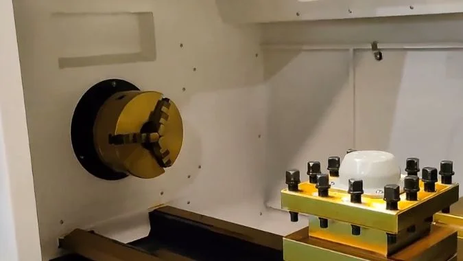
A nameplate can say 5000 r/min and still not be the speed the job may run. The chuck has its own limit. Centrifugal force on the jaws eats clamping force as RPM rises1. The shop then uses the lower of the two clocks. That split is nameplate RPM versus the chuck’s rated safe speed.
What Is the Difference Between Spindle Nameplate RPM and the Chuck’s Rated Safe Speed?
Shops use the spindle’s maximum RPM as the chuck’s limit. The chuck can already be unsafe at that speed. The two nameplates must be compared.
Spindle nameplate RPM is how fast the spindle or motor may turn. The chuck’s rated safe speed is how fast the chuck may turn and still keep a safe grip. The two limits are not the same. The lower one is the shop cap.
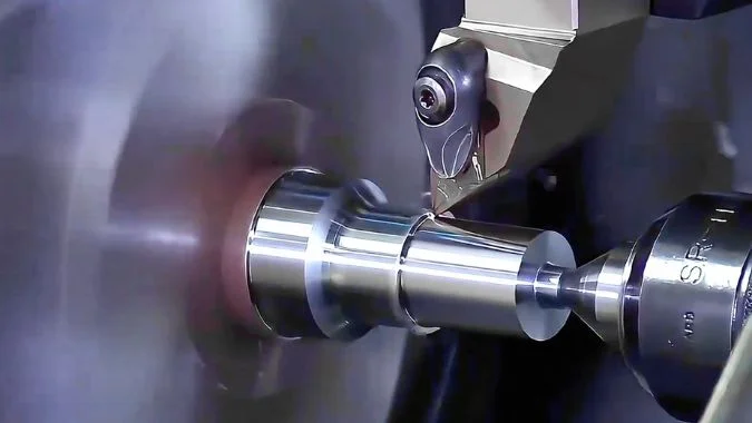
What the spindle nameplate states
Spindle nameplate RPM is the speed the spindle design allows. Bearings, lubrication, motor power, and machine structure set it2. The plate usually shows a rated speed and a maximum speed. Rated speed is the stable working point. Maximum speed is the design limit. Running past it damages the spindle. That number is a motor and bearing story. It is not a gripping story.
What the chuck rated safe speed states
The chuck maker sets a maximum permissible speed from structure, clamping force, and centrifugal force. Past that speed, jaws throw outward and grip falls. The workpiece can leave the chuck. Diameter, jaw weight, clamping force, and balance set this limit. One Kitagawa family lists 7000, 6000, 4500, and 3600 r/min across sizes3. The supplier speed-to-clamping-force curve is the check. The chuck limit must sit above the spindle max, with a margin.
Why the two clocks are not interchangeable
The spindle can turn faster than the chuck may carry a part. The chuck can also be rated above a modest spindle. Daily use still follows the lower clock. Mixing the two labels on a quote hides the real cap. A shop that chases only the spindle number still meets the chuck plate on the floor.
| Clock | What it measures | What sets it | What happens past it |
|---|---|---|---|
| Spindle nameplate RPM | How fast the spindle may turn | Bearings, lube, motor, structure | Spindle damage |
| Chuck rated safe speed | How fast the chuck may turn with a safe grip | Diameter, jaws, force, balance | Grip decay, part can fly |
| Shop cap | The lower of the two | Both plates, plus a margin | The job must not exceed this |
Why Does a Larger Chuck Lower the Usable RPM Even if the Spindle Can Spin Faster?
A larger body looks like more grip. At speed it throws more mass outward, so usable RPM falls even when the spindle can go higher.
A larger chuck lowers usable RPM because rim speed and jaw centrifugal force rise with diameter. Clamping force decays, vibration grows, and the safe cap sits below the spindle’s extra speed. Bigger is not the default.

Linear speed and the throw
At the same RPM, a larger chuck has a higher rim speed4. Chuck body and jaws then see a sharp rise in centrifugal force. Grip can loosen. The part can leave the jaws. RPM rises, and jaws are thrown outward, and clamping force drops. A larger chuck and heavier jaws make that throw worse. The part can shift in the cut. Heavy cutting then needs leftover grip at the top speed, not only the static catalog force.
Rigidity and balance
A large chuck is a large mass. The spindle and flange must hold it. Weak support at speed starts vibration and marks the surface. Dynamic balance is also harder on a large body5. Unbalance at speed grows noise and shake6. The usable RPM then falls to keep the assembly quiet. The spindle motor can still have unused speed.
Match the body to the part
Nominal chuck diameter maps to workpiece range and spindle nose. Bigger is not the default. External clamp max must exceed the part OD with a margin. Jaws at the last tooth lose force. Internal clamp needs enough jaw stroke. The flange must match the spindle nose, or the chuck will not mount. Horizontal CNC lathes often use 100–500 mm bodies. Common sizes include 160, 260, 400, and 500 mm7. Vertical lathes can exceed 500 mm8. Large disks want low speed and high torque. Small shafts want a stable high-speed band.
| Driver | What a larger chuck does | Effect on usable RPM |
|---|---|---|
| Rim speed | Higher at the same r/min | Safe cap falls |
| Jaw throw | More mass thrown outward | Grip decays sooner |
| Mass on the nose | More demand on spindle and flange | Vibration at speed |
| Balance | Harder to keep even | Noise and shake rise |
| Fit to the part | Only needed when the OD requires it | Extra diameter is unused risk |
How Should Jaw Mass and Counterweights Be Counted Inside the Chuck Speed Rating?
A speed chart that ignores jaw mass is a paper limit. Heavy jaws and a wide grip then eat the force the nameplate still claims.
Jaw mass inside the chuck speed rating includes the base jaw, top jaw, and moving hardware. Heavier jaws and a larger center-of-gravity radius raise centrifugal force with the square of RPM. Counterweights can offset that throw.
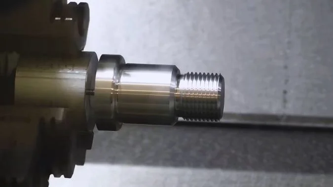
Count the moving mass
The core check is how jaw centrifugal force offsets clamping force. Force rises with the square of speed9. Effective grip then falls. A workpiece can fly, or a jaw can fail. Heavier jaws raise centrifugal force at the same RPM, so grip loss is worse. The counted mass is one jaw: base jaw, top jaw, and connecting parts. A booster screw structure must count the whole moving mass.
Counterweights and center of gravity
Some chucks add centrifugal compensation. A reverse mechanism fights the outward throw and holds grip at higher speed. That option is part of the speed rating, not a shop add-on after the quote. Jaw center-of-gravity radius also matters. A jaw sitting farther out raises centrifugal force. Large-diameter work moves that radius out, so rated speed should fall. A wide grip on a large disk is then a lower RPM job, even on the same chuck body.
How makers set the number
Chuck makers often set maximum speed at the point where centrifugal force reaches two-thirds of maximum clamping force10. Weak points still need a strength check at that speed. Jaw-seat keys, bolts, and screws take shear and torsion. Thin keys, few bolts, or a low bolt grade fail first. Workpiece weight, center of gravity, a tailstock or steady rest, and cutting force then change the real safe speed. A safety factor belongs on the shop number. The chuck’s own plate is not the last word.
| Item to count | Why it changes the rating |
|---|---|
| Base jaw + top jaw + hardware | Moving mass sets centrifugal force |
| Booster-screw moving parts | Extra mass still throws outward |
| Center-of-gravity radius | A wider grip raises force at the same RPM |
| Counterweight / compensation | Offsets throw and can hold grip at higher speed |
| 2/3 clamping-force rule | Common maker definition of max speed |
| Keys, bolts, screws | Strength floor at that speed |
| Part weight, rest, cut force | Shop safety factor on top of the plate |
Why Can a Brochure “5000 r/min Spindle” Still Be Capped at a Much Lower Chuck Speed?
A brochure 5000 r/min is the spindle’s own ceiling. The chuck plate on the body is often far lower, and that plate is the one that binds.
A brochure 5000 r/min spindle is still capped at a lower chuck speed because the chuck and fixture set a new limit. The chuck nameplate, jaw type, balance, G50, and available torque all sit below that printed 5000.
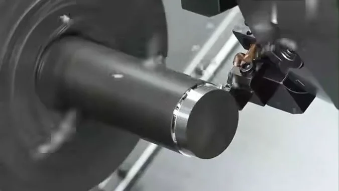
The brochure number is the spindle
5000 r/min on a CNC lathe brochure is the spindle’s own limit. In use, the chuck and fixture become the new cap. The two labels are not the same. A 5000 r/min line does not mean a chucked part may run at 5000. The chuck body and the front guard door carry the permissible speed and the permissible clamp pressure. Those are the maker’s safety bounds from strength, jaw type, and balance. The spindle must not pass them.
What else pulls the cap down
Special jaws and non-standard soft steel jaws clamp less efficiently and throw worse, so the allowed speed falls again. A nut that sits outside the chuck rim is a further cut. An unbalanced workpiece at high speed shakes the machine and the grip. Work near the chuck limit needs a balanced part and clamp pressure at the allowed maximum.
G96 constant surface speed11 is a hard program limit. As diameter falls, theoretical RPM soars. G50 must set a spindle max so the machine and the fixture stay inside strength12. G50 S2000 is one such cap. Speed then shall not exceed 2000 r/min.
High RPM also does not mean the cut can be driven. Short torque or power in the used band leaves the spindle spinning without feeding the tool. Faster spindle speed is not always better on that cut. Speed should then fall on purpose. Drive type, bearings, and lubrication already set the spindle max. Brochure values are often an ideal test. Load on the floor takes a discount.
Read the plates before the brochure
The chuck plate and the guard door are the first check. Workpiece weight, balance, and the cutting method then set a safe speed. The brochure figure is not the operating basis.
| Limit | Typical source | What it does to 5000 r/min |
|---|---|---|
| Spindle brochure | Ideal spindle test | Prints 5000 |
| Chuck nameplate | Body and guard door | New, often lower, cap |
| Special / soft jaws | Extra throw, weaker clamp | Cap falls again |
| Unbalanced part | Vibration at speed | Cap must fall |
| G96 without G50 | RPM soars as diameter falls | Program must lock a max |
| Short torque in the band | Motor cannot drive the cut | Speed should fall on purpose |
Conclusion
Specify chuck diameter only after the chuck speed limit clears the spindle max with a margin. Size then follows the part. The brochure RPM is not the shop cap.
-
"Factors affecting grip force: Anatomy, mechanics, and referent …", https://pmc.ncbi.nlm.nih.gov/articles/PMC4013148/. Engineering mechanics demonstrates that centrifugal force acting on rotating chuck jaws increases with the square of rotational velocity, creating an outward force that opposes the mechanical clamping force and reduces net gripping capacity. Evidence role: mechanism; source type: research. Supports: the inverse relationship between rotational speed and effective clamping force due to centrifugal effects. ↩
-
"Machine Tool Spindle Bearings Types & Selection Guide", https://pibsales.com/tutorials/machine-tool-spindle-bearings-types-selection-guide/?srsltid=AU7gw4Woq0f0qZH3Pq9Ku02G0SH7bVD6ib4qKPdLvf7ktGDbQzJ2yuaX. Machine tool design literature identifies bearing DN values (bearing bore diameter × RPM), lubrication system capacity, motor power curves, and structural dynamics as the principal factors establishing spindle speed envelopes, with each subsystem imposing distinct operational limits. Evidence role: general_support; source type: education. Supports: the primary engineering constraints that determine maximum spindle operating speeds. ↩
-
"Forming Quality Research on the Variable-Diameter Section …", https://pmc.ncbi.nlm.nih.gov/articles/PMC9414841/. Manufacturer specifications across the chuck industry demonstrate that maximum rated speeds decrease with increasing chuck diameter, reflecting the physics of centrifugal forces and the engineering constraints of maintaining safe clamping at higher peripheral velocities. Evidence role: case_reference; source type: other. Supports: the inverse relationship between chuck diameter and rated maximum speed. Scope note: The specific Kitagawa values cited are manufacturer-specific, though the inverse relationship is industry-wide ↩
-
"Tangential speed", https://en.wikipedia.org/wiki/Tangential_speed. Rotational kinematics establishes that tangential (rim) velocity equals the product of angular velocity and radius (v = ωr), meaning that at constant RPM, peripheral speed increases proportionally with diameter. Evidence role: mechanism; source type: encyclopedia. Supports: the linear relationship between rotational radius and tangential velocity at constant angular velocity. ↩
-
"Rotating Machinery Rotor Balancing", https://rotorlab.tamu.edu/me459/Rotor%20Balancing/Rotating_Machinery_Rotor_Balancing.pdf. Rotating machinery engineering demonstrates that balancing precision requirements become more stringent with increasing diameter and mass, as unbalance forces scale with both mass and the square of the radius, making larger components more sensitive to mass distribution asymmetries. Evidence role: general_support; source type: research. Supports: the increased difficulty of achieving dynamic balance in larger rotating components. ↩
-
"Study on the Influence of Unbalanced Phase Difference …", https://www.mdpi.com/1424-8220/25/6/1691. Vibration engineering establishes that unbalanced rotating masses generate periodic forces proportional to the square of rotational speed, producing vibration amplitudes and noise levels that increase dramatically with RPM, potentially causing surface finish degradation and accelerated bearing wear. Evidence role: mechanism; source type: research. Supports: the relationship between rotational imbalance and vibration severity. ↩
-
"Lathe Chucks: Clamp, Center, and Control Your Work", https://www.mscdirect.com/resources/buying-guides/lathe-chucks. Machine tool industry specifications document that horizontal CNC lathes commonly employ chucks ranging from small precision sizes around 100-200mm for bar work to larger capacities of 400-500mm for heavier components, with size selection driven by workpiece dimensions and machine capacity. Evidence role: general_support; source type: institution. Supports: typical chuck size ranges used in horizontal CNC lathe applications. ↩
-
"Lathe Chuck Types, Mounting & 3-Jaw vs 4-Jaw Guide", https://cncwmt.com/qa/everything-you-need-to-know-about-lathe-chuck/. Machine tool industry data indicates that vertical lathes and vertical turning centers commonly accommodate workholding fixtures ranging from 500mm to several meters in diameter, designed for large-diameter, relatively short workpieces such as rings, flanges, and disks. Evidence role: general_support; source type: institution. Supports: the typical chuck size ranges for vertical lathe configurations. ↩
-
"Centrifugal force", https://en.wikipedia.org/wiki/Centrifugal_force. Classical mechanics establishes that centrifugal force is proportional to the square of angular velocity (F = mω²r), meaning that doubling rotational speed quadruples the outward force on rotating components. Evidence role: mechanism; source type: encyclopedia. Supports: the mathematical relationship between rotational speed and centrifugal force. ↩
-
"Safe speeds for large chucks", https://www.practicalmachinist.com/forum/threads/safe-speeds-for-large-chucks.199517/. Manufacturing standards organizations document that chuck speed ratings typically incorporate safety factors where centrifugal forces are limited relative to static clamping capacity, though specific ratios vary by manufacturer and application. Evidence role: expert_consensus; source type: institution. Supports: the industry practice of setting chuck speed ratings based on centrifugal force thresholds. Scope note: The exact two-thirds ratio may be manufacturer-specific rather than a universal standard ↩
-
"G96 G-Code: Constant Surface Speed CNC Programming", https://www.cnccookbook.com/g96-g-code-constant-surface-speed-cnc/. CNC programming standards define G96 as the command that activates constant surface speed mode, automatically adjusting spindle RPM as tool position changes to maintain consistent cutting velocity at the workpiece surface. Evidence role: definition; source type: institution. Supports: the function of G96 in CNC programming standards. ↩
-
"Any tips on calculating G50 and G96 in CNC machining?", https://www.facebook.com/groups/769782850345135/posts/1298664774123604/. CNC programming standards specify that G50 with an S parameter establishes an upper spindle speed limit, preventing the spindle from exceeding a specified RPM regardless of other programmed commands, particularly important when using constant surface speed mode. Evidence role: definition; source type: institution. Supports: the function of G50 in limiting maximum spindle speed. ↩

Chris Lu
Leveraging over a decade of hands-on experience in the machine tool industry, particularly with CNC machines, I'm here to help. Whether you have questions sparked by this post, need guidance on selecting the right equipment (CNC or conventional), are exploring custom machine solutions, or are ready to discuss a purchase, don't hesitate to CONTACT Me. Let's find the perfect machine tool for your needs.