

Was ist ein vertikales/horizontales Bearbeitungszentrum?
Komplexe Teile erfordern oft mehrere Maschinen und Rüstvorgänge. Jedes neue Einrichten kostet Zeit, Arbeitsaufwand und erhöht das Risiko von Positionierfehlern.
Ein vertikal-horizontales Bearbeitungszentrum ist eine CNC-Werkzeugmaschine, die vertikales und horizontales Schneiden in einem System vereint. Es kann die Oberseite und mehrere Seiten eines Werkstücks mit nur einer Aufspannung bearbeiten, was die Flexibilität, Genauigkeit und Produktionseffizienz verbessert.
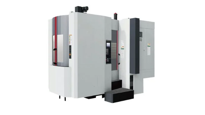
Ein vertikal-horizontales Bearbeitungszentrum – auch Universal- oder Fünf-Seiten-Bearbeitungszentrum genannt – kombiniert vertikales und horizontales Fräsen, Bohren, Aufbohren und Gewindeschneiden auf einer einzigen CNC-Plattform. Durch die automatische Neuausrichtung der Spindel oder des Arbeitstisches werden die Oberseite und vier Seitenflächen in einer einzigen Aufspannung bearbeitet, was Einspannfehler, Vorrichtungen und Zykluszeiten drastisch reduziert1 bei komplexen, mehrseitigen Teilen.
Wie ist die Struktur eines vertikal-horizontalen Bearbeitungszentrums aufgebaut?
Eine komplexe Maschinenstruktur kann schwer verständlich erscheinen. Ohne Kenntnis der Hauptkomponenten könnten Käufer ungeeignete Spezifikationen wählen oder den Wartungsbedarf unterschätzen.
Ein vertikal-horizontales Bearbeitungszentrum integriert zwei unabhängige Spiegeleinheiten – eine dedizierte vertikale und eine dedizierte horizontale – auf einem einzigen, hochsteifen Gussmaschinenbett. Diese Doppelspindelstruktur, die um einen zentralen CNC-Drehtisch herum aufgebaut ist, ermöglicht den direkten, sequenziellen Wechsel zwischen vertikaler Oberflächenbearbeitung und horizontaler Seitenbearbeitung am aufgespannten Werkstück ohne sekundäres Einrichten.
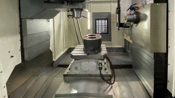
Wichtige strukturelle Komponenten
Das Fundament der Maschine ist ein hochbelastbares, hochfestes Gussbett, das mit internen Verrippungen konstruiert ist, um Schnittvibrationen zu absorbieren2 und dynamische Verformungen beim schweren Fräsen zu eliminieren.
Auf diesem gemeinsamen Bett ist ein Doppelständer-Layout mit "A-Rahmen"-Ständerdesign montiert, das eine überlegene Torsions- und Biegesteifigkeit bietet. Anstatt einen gelenkigen Schwenkkopf zu verwenden, integriert das System zwei dedizierte, unabhängige Spindeln:
- Vertikale Spiegeleinheit: Montiert am vertikalen Ständer für das Fräsen, Bohren und Gewindeschneiden der Oberseite.
- Horizontale Spiegeleinheit: Neben dem Tisch montiert für Tiefbohrungen und vierseitiges Fräsen.
- Integrierter Antrieb & Führungen: Die X-Achsen-Antriebsaufnahme und das Endlager sind integral mit dem Schlitten gegossen, um die Übertragungssteifigkeit zu maximieren; sie werden über alle Achsen durch hochbelastbare Rollenlinearführungen gestützt.
Wie die Doppelspindelstruktur die fünfseitige Bearbeitung unterstützt
Die Bearbeitung aller fünf freiliegenden Flächen in einer einzigen Aufspannung beruht auf der Koordination zwischen dem zentralen CNC-Rundtisch und dem unabhängigen Doppelspindel-Layout:
- Oberflächenbearbeitung: Die dedizierte vertikale Spindel fährt ab, um die obere Ebene, Taschen und vertikale Montagebohrungen zu bearbeiten.
- Vierseitenbearbeitung: Die horizontale Spindel greift seitlich am Werkstück an, während der zentrale Rundtisch um 360 Grad indexiert, um jede der vier Seitenflächen nacheinander zu präsentieren.
Da beide Spindeln mit dedizierten, festen Ausrichtungen arbeiten und nicht mit einem indexierenden Schwenkkopf, vermeidet die Maschine mechanisches Umkehrspiel, Aufspannungsdurchbiegung und Verschleiß bei der Winkelpositionierung, wie sie bei universellen Schwenkköpfen üblich sind. Diese starre Doppelstationsarchitektur reduziert manuelle Handhabung drastisch, bewahrt einheitliche Bezugssysteme und liefert maximale Schnittstabilität über alle fünf Oberflächen hinweg.
Welches Präzisionsniveau kann ein vertikal-horizontales Bearbeitungszentrum erreichen?
Kleine Positionierfehler können ein teures, komplexes Bauteil ruinieren. Wiederholtes Umspannen verschlimmert dieses Problem, da jede neue Einrichtung einen weiteren Referenzfehler einführen kann.
Ein gut konfiguriertes vertikal-horizontales Bearbeitungszentrum kann eine Positioniergenauigkeit von etwa 0,01 mm und eine Wiederholgenauigkeit von etwa 0,008 mm erreichen. Ein Präzisionsrundtisch kann eine Teilungsgenauigkeit von etwa ±2 Winkelsekunden bieten, wobei die tatsächlichen Ergebnisse von der Maschine, der Umgebung, der Werkzeugausstattung und dem Prozess abhängen.
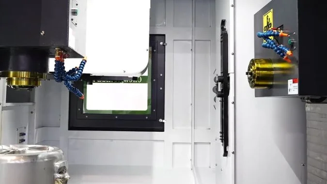
Typische Genauigkeitsindikatoren
Die Positioniergenauigkeit zeigt, wie genau eine Achse ihre programmierte Position erreicht. Die Wiederholgenauigkeit zeigt, wie konsistent die Achse an denselben Ort zurückkehrt. Beide Werte sind wichtig, beschreiben jedoch unterschiedliche Aspekte der Maschinenleistung.
Die Genauigkeit des Rundtisches ist ebenfalls wichtig. Ein kleiner Winkelfehler kann an der Kante eines breiten Werkstücks einen größeren Maßfehler verursachen. Präzisionsmesssysteme und eine zuverlässige Tischklemmung helfen, dieses Problem zu kontrollieren.
| Genauigkeitsmerkmal | Typischer Referenzwert | Was dies anzeigt |
|---|---|---|
| Lineare Positioniergenauigkeit | Etwa 0,01 mm | Genauigkeit der befohlenen Achsenbewegung |
| Lineare Wiederholgenauigkeit | Etwa 0,008 mm | Konsistenz der wiederholten Achsenbewegung |
| Rundtisch-Teilungsgenauigkeit | Etwa ±2 Bogensekunden | Genauigkeit des befohlenen Tischwinkels |
| Wiederholgenauigkeit der Rundtisch-Teilung | Etwa ±2 Bogensekunden | Konsistenz bei der Rückkehr zu einem Winkel |
Diese Zahlen sind Referenzwerte und keine Garantie für jede Maschine. Einige hochwertige Modelle können engere Toleranzen erreichen. Basismodelle können eine geringere Genauigkeit aufweisen. Die Maschinenspezifikation sollte immer den Messstandard und die Testbedingungen angeben.
Faktoren, die die tatsächliche Bauteilgenauigkeit beeinflussen
Die endgültige Bauteiltoleranz hängt nicht allein von der Maschinenspezifikation ab. Temperaturänderungen können die Maschinenstruktur und das Werkstück ausdehnen3. Werkzeugverschleiß kann den Schnittdurchmesser verändern. Eine schwache Aufspannung kann dazu führen, dass sich das Teil bewegt. Eine schlechte Werkzeugauswuchtung kann Vibrationen verursachen und die Oberflächenqualität mindern.
Das CNC-System kann Fehlerkompensation nutzen, um die Achsensteuerung zu verbessern4. Glasmaßstäbe und hochauflösende Encoder können ebenfalls eine stabilere Positionierung unterstützen. Dennoch muss der Bearbeitungsprozess auf die Leistungsfähigkeit der Maschine abgestimmt sein.
Die Komplettbearbeitung in einer Aufspannung bietet einen weiteren Genauigkeitsvorteil. Wiederholte Rüstvorgänge können die Beziehung zwischen Bohrungen, Oberflächen und Bezugspunkten verändern. Ein Vertikal-Horizontal-Bearbeitungszentrum hält mehr Merkmale in einem Koordinatensystem. Dieser Aufbau kann die Lagebeziehungen verbessern, selbst wenn die grundlegende Maschinentoleranz unverändert bleibt.
Regelmäßige Kalibrierung ist weiterhin erforderlich. Ball-Bar-Tests, Lasermessungen, Spindelinspektionen und Drehachsenprüfungen5 können Verschleiß aufdecken, bevor es zu Ausschussteilen kommt. Stabile Fundamente und kontrollierte Werkstatttemperaturen helfen der Maschine zudem, ihre Präzision über die Zeit zu erhalten.
Verringert der Einsatz eines vertikal-horizontalen Bearbeitungszentrums den Platzbedarf der Anlage?
Fabrikfläche ist teuer, und separate Maschinen benötigen mehr als nur ihre eigene Grundfläche. Sie erfordern auch Gänge, Wartungszugänge, Spänefördersysteme und Ladezonen.
Ein Vertikal-Horizontal-Bearbeitungszentrum kann den gesamten Platzbedarf reduzieren, wenn es sowohl ein vertikales als auch ein horizontales Bearbeitungszentrum ersetzt. Seine individuelle Stellfläche ist nicht klein, aber eine kombinierte Maschine verbraucht insgesamt etwa 30 % bis 50 % weniger Platz als zwei separate Maschinen, einschließlich der unterstützenden Bereiche.
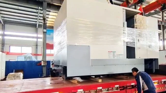
Einzelmaschinengröße im Vergleich zum gesamten Produktionsraum
Ein Vertikal-Horizontal-Bearbeitungszentrum ist in der Regel größer als ein vertikales Bearbeitungszentrum mit vergleichbarer Arbeitskapazität. Die kombinierte Maschine benötigt Platz für ihren Drehmechanismus, das Werkzeugmagazin, die Einhausung, den Späneförderer und die Bewegungen in mehrere Richtungen. Ihr Platzbedarf kann sich dem eines horizontalen Bearbeitungszentrums in der gleichen Größenklasse annähern oder dieses leicht übertreffen.
Der korrekte Vergleich ist nicht immer eine kombinierte Maschine gegenüber einer Einzelzweckmaschine. Eine Fabrik benötigt möglicherweise sowohl vertikale als auch horizontale Funktionen. In diesem Fall ist der praktische Vergleich ein Vertikal-Horizontal-Zentrum gegenüber einem Vertikalzentrum plus einem Horizontalzentrum.
| Anordnung der Betriebsmittel | Relativer Platzbedarf | Geeigneter Produktionsbedarf |
|---|---|---|
| Ein Standard-VMC | Niedrig | Hauptsächlich Oberflächen- und Plattenbearbeitung |
| Ein Standard-HMC | Mittel bis hoch | Hauptsächlich Seiten- und Gehäusebearbeitung |
| Ein VMC plus ein HMC | Höchste | Getrennte vertikale und horizontale Prozesse |
| Ein Vertikal-Horizontal-Bearbeitungszentrum | Mittel bis hoch | Häufige mehrseitige Bearbeitung in einer Aufspannung |
Eine kombinierte Maschine kann den Platz zwischen zwei Maschinen einsparen. Zudem reduziert sie den Bedarf an separaten Späneförderern, Kühlanlagen, Ladestationen und Werkzeugspeichern. Diese Änderungen erklären, warum die gesamte Platzersparnis etwa 30 % bis 50 % erreichen kann. Der tatsächliche Prozentsatz hängt von der Maschinenaufstellung und den örtlichen Sicherheitsvorschriften ab.
Wann der Platzvorteil zum Tragen kommt
Der Platzvorteil besteht nur dann, wenn der Produktionsprozess beide Bearbeitungsrichtungen erfordert. Eine Werkstatt, die nur flache Platten herstellt, profitiert möglicherweise mehr von einem kompakten vertikalen Bearbeitungszentrum. Ein Werk, das ausschließlich Gehäuseteile in großen Mengen fertigt, bevorzugt unter Umständen ein dediziertes horizontales Bearbeitungszentrum.
Eine Vertikal-Horizontal-Maschine bietet eine höhere Platzeffizienz, wenn Werkstücke häufig zwischen vertikalen und horizontalen Arbeitsgängen bewegt werden müssen. Sie reduziert auch das Zwischenlager für unfertige Erzeugnisse, da die Teile nicht zwischen zwei getrennten Maschinen warten müssen. Die Transportwege werden kürzer und es werden möglicherweise weniger Vorrichtungen benötigt.
Die Maschine benötigt weiterhin ausreichend Wartungsfreiraum. Das Bedienpersonal benötigt einen sicheren Zugang zum Tisch, zum Werkzeugmagazin, zum Kühltank und zum Schaltschrank. Der Investitionsplan sollte daher die vollständige Installationsfläche berücksichtigen und nicht nur die in einem Katalog angegebenen Maschinenabmessungen.
Welche Branchen benötigen den Einsatz von vertikal-horizontalen Bearbeitungszentren?
Komplexe Bauteile weisen oft enge Toleranzen und Merkmale auf mehreren Seiten auf. Getrennte Arbeitsgänge können die Produktion verlangsamen und zu Fehlern bei der Ausrichtung zwischen verbundenen Flächen führen.
Vertikal-Horizontal-Bearbeitungszentren werden hauptsächlich in der Automobilindustrie, der Luft- und Raumfahrt, im Maschinenbau, im Formenbau, im Energiesektor und in der allgemeinen Fertigungstechnik eingesetzt. Sie sind am nützlichsten für komplexe Teile, die präzise Bohrungen, Taschen, Ebenen und abgewinkelte Merkmale auf mehreren Oberflächen erfordern.
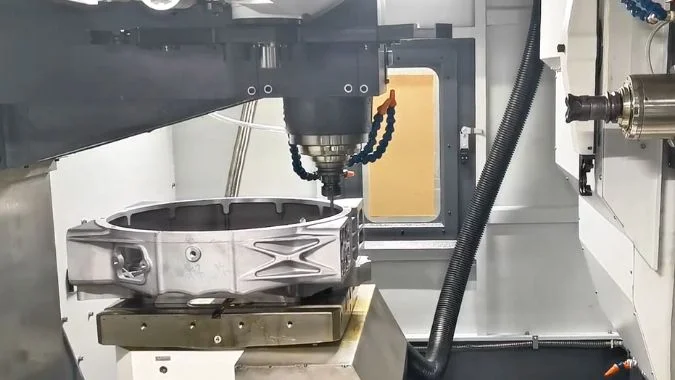
Automobilfertigung
Die Automobilproduktion umfasst Motorteile, Getriebegehäuse, Fahrwerkskomponenten, Batteriegehäuse6, und Spezialfahrzeugteile. Viele dieser Komponenten weisen Bohrungen und bearbeitete Flächen auf mehreren Seiten auf.
Ein vertikal-horizontales Bearbeitungszentrum kann mehrere Prozesse nach einer einzigen Einspannung abschließen. Das Werkzeugmagazin kann Bohrer, Schaftfräser, Gewindebohrer, Ausdrehwerkzeuge und Planfräser aufnehmen. Das CNC-System kann jedes Werkzeug automatisch auswählen. Dieser Prozess reduziert manuelle Arbeit und unterstützt eine konsistentere Produktion.
Die Maschine ist besonders nützlich für die Produktion kleiner und mittlerer Stückzahlen von Automobilteilen mit komplexem Design. Dedizierte Transferstraßen bleiben bei extrem hohen Produktionsvolumina möglicherweise effizienter.
Luft- und Raumfahrt sowie Präzisionsmaschinenbau
Luft- und Raumfahrtteile verwenden häufig Aluminium, Titan, Edelstahl und hitzebeständige Legierungen7. Diese Materialien erfordern stabile Schnittbedingungen. Komponenten für die Luft- und Raumfahrt haben zudem strenge Anforderungen an Maßgenauigkeit, Merkmalslage und Oberflächenqualität.
Die starre Struktur eines vertikal-horizontalen Zentrums unterstützt schwere und präzise Zerspanung. Die Mehrachssteuerung ermöglicht es der Maschine zudem, schwierige Oberflächen zu erreichen. Weniger Rüstvorgänge schützen die Beziehung zwischen kritischen Merkmalen.
Hersteller von Präzisionsmaschinen nutzen diese Maschinen für Gehäuse, Ventilkörper, Robotikteile, Instrumentenkomponenten und Produktionsanlagen. Die Ausrüstung unterstützt sowohl Prototypenarbeiten als auch Wiederholfertigung.
Formenbau und allgemeine industrielle Produktion
Die Formenherstellung erfordert präzise Kavitäten, ebene Referenzflächen, Kühlkanäle und Seitenmerkmale. Ein kombiniertes Bearbeitungszentrum kann die Hauptkavität und mehrere Seitenflächen bearbeiten, ohne die Formbasis auf eine andere Maschine bewegen zu müssen. Dieser Ansatz kann den Produktionszyklus verkürzen und den Ausrichtungsaufwand reduzieren.
| Industrie | Typische Teile | Hauptnutzen |
|---|---|---|
| Automobilindustrie | Getriebegehäuse, Motorenteile, Halterungen | Schnellere Multiprozess-Fertigung |
| Luft- und Raumfahrt | Strukturbauteile, Gehäuse, Präzisionsrahmen | Stabile Genauigkeit und weniger Rüstvorgänge |
| Präzisionsmaschinenbau | Ventilgehäuse, Roboterteile, Instrumentengehäuse | Bessere Merkmalsbeziehungen |
| Formenbau | Formaufbauten, Kavitäten, seitliche Bohrungen | Kürzere Rüst- und Ausrichtzeiten |
| Energietechnik | Pumpengehäuse, Turbinenteile, Verteilerblöcke | Flexible Bearbeitung von Großteilen |
| Allgemeiner Maschinenbau | Rahmen, Vorrichtungen, kundenspezifische Komponenten | Breite Prozesskapazität |
Die Maschine kann auch manuelle Eingriffe reduzieren. Die CNC-Steuerung verwaltet die Achsenbewegung, Spindeldrehzahl, Werkzeugwechsel und Tischindexierung. Automatisierung kann den Arbeitskräftebedarf senken und Handhabungsfehler begrenzen. Qualifiziertes Personal ist weiterhin für Programmierung, Vorrichtungsplanung, Werkzeugauswahl, Inspektion und Wartung erforderlich.
Die wesentlichen Nachteile müssen ebenfalls beachtet werden. Ein vertikal-horizontales Bearbeitungszentrum hat höhere Anschaffungskosten als viele Einzelfunktionsmaschinen. Die Struktur ist wartungsintensiver. Die Programmierung kann anspruchsvoller sein, und Kollisionsrisiken können zunehmen, wenn sich Tisch und Spindel durch mehrere Positionen bewegen. Eine geeignete Maschine erfordert daher starke technische Unterstützung, klare Bedienerschulungen, zuverlässige Ersatzteile und einen Prozess, der ihre volle Leistungsfähigkeit ausschöpfen kann.
Schlussfolgerung
Ein vertikal-horizontales Bearbeitungszentrum kombiniert mehrseitiges Fräsen, hohe Präzision, weniger Rüstvorgänge und eine effiziente Raumnutzung, was es wertvoll für komplexe Teile in anspruchsvollen Fertigungsindustrien macht.
-
"Die Vorteile der 5-Achs-CNC-Bearbeitung", https://www.methodsmachine.com/blog/benefits-of-5-axis-machining/. Die Ein-Aufspannungs-Bearbeitung eliminiert Umspannfehler, indem konsistente Bezugspunkte während der gesamten Arbeitsgänge beibehalten werden. Dies reduziert kumulative Positionierfehler und verbessert die Genauigkeit zwischen den Merkmalen, wie in der Präzisionsfertigungsforschung zu Mehrachsen-Bearbeitungsstrategien nachgewiesen. Nachweisrolle: Mechanismus; Quellentyp: Fachartikel. Unterstützt: Fehlerreduzierungsmechanismen bei der mehrseitigen Ein-Aufspannungs-Bearbeitung. Anmerkung zum Geltungsbereich: Tatsächliche Verbesserungen hängen von der Teilegeometrie, dem Vorrichtungsdesign und der Maschinenkapazität ab. ↩
-
"Dämpfung von Rohrleitungsvibrationen durch interne Dämpfung und …", https://pmc.ncbi.nlm.nih.gov/articles/PMC10119187/. Gusseisen bietet aufgrund seiner Graphitlamellen-Mikrostruktur eine überlegene Schwingungsdämpfung im Vergleich zu geschweißten Stahlkonstruktionen. Interne Rippenmuster erhöhen die dynamische Steifigkeit durch eine Steigerung des Flächenträgheitsmoments bei gleichzeitiger Materialeffizienz, so die Forschung zum Werkzeugmaschinendesign. Beweisrolle: Mechanismus; Quellentyp: Forschung. Unterstützt: Schwingungsdämpfungsmechanismen in Werkzeugmaschinenstrukturen aus Gusseisen. ↩
-
"Identifizierung einer Werkstück-Temperaturkompensation …", https://pmc.ncbi.nlm.nih.gov/articles/PMC9741256/. Die Wärmeausdehnung von Werkzeugmaschinenstrukturen und Werkstücken kann 40-70 % des gesamten Positionierfehlers bei Präzisionsbearbeitungsvorgängen ausmachen, wobei Temperaturschwankungen eine vorhersehbare lineare Ausdehnung verursachen, die eine Kompensation durch Umgebungskontrolle oder Echtzeit-Korrektursysteme erfordert. Beweisrolle: Mechanismus; Quellentyp: Fachartikel. Unterstützt: Thermische Auswirkungen auf die Maßhaltigkeit bei der Präzisionsbearbeitung. ↩
-
"Roll-, Nick- und Gierfehler bei CNC-Fräsmaschinen", https://www.academia.edu/49581493/Roll_Pitch_and_Yaw_Errors_in_CNC_Milling_Machine_Tools. Moderne CNC-Steuerungen implementieren softwarebasierte Fehlerkompensation für geometrische Fehler (Nick-, Gier-, Geradheits-, Rechtwinkligkeitsfehler) und thermische Drift durch Anwendung von Korrekturwerten, die aus Kalibrierungsmessungen abgeleitet wurden, auf die Sollpositionen. Dies erzielt signifikante Verbesserungen der volumetrischen Genauigkeit ohne mechanische Modifikationen. Beweisrolle: Mechanismus; Quellentyp: Fachartikel. Unterstützt: Fehlerkompensationstechniken in der CNC-Werkzeugmaschinensteuerung. Hinweis zum Geltungsbereich: Die Wirksamkeit erfordert eine genaue Fehlerabbildung und setzt wiederholbare Fehlermuster voraus. ↩
-
"Ressourcen: Kalibrierungsverfahren", https://www.nist.gov/pml/owm/laboratory-metrology/documentary-standards-and-resources/calibration-procedures. Die Ballbar-Prüfung gemäß ISO 230-4 und die Laserinterferometrie gemäß ISO 230-2 stellen Standardmethoden zur Bewertung der geometrischen und Positioniergenauigkeit von CNC-Werkzeugmaschinen dar und ermöglichen die Erkennung von Achsenfehlern, thermischer Drift und mechanischem Verschleiß, bevor diese die Toleranzgrenzen überschreiten. Beweisrolle: allgemeine Unterstützung; Quellentyp: Institution. Unterstützt: Standardisierte Kalibrierungsmethoden zur Überprüfung der Genauigkeit von CNC-Werkzeugmaschinen. ↩
-
"Bearbeitung von Getriebegehäusen – Trace-A-Matic", https://www.traceamatic.com/cnc-products/transmission-housings.html. Getriebegehäuse und Motorblöcke erfordern die Bearbeitung von Montageflächen, Lagerbohrungen und Schraubenlöchern auf mehreren Seiten mit strengen Positionstoleranzen. Dies macht sie zu geeigneten Kandidaten für mehrseitige Bearbeitungsstrategien, die die Bezugskonsistenz wahren, wie in der Dokumentation zu Fertigungsprozessen in der Automobilindustrie beschrieben. Beweisrolle: Fallbeispiel; Quellentyp: Ausbildung. Unterstützt: Automobilkomponenten, die mehrseitige Bearbeitungsvorgänge erfordern. ↩
-
"Titanlegierungen", https://en.wikipedia.org/wiki/Titanium_alloys. Strukturbauteile in der Luft- und Raumfahrt verwenden aufgrund ihres Festigkeits-Gewichts-Verhältnisses und ihrer Hochtemperaturleistung häufig Aluminiumlegierungen (7075, 2024), Titanlegierungen (Ti-6Al-4V) und Superlegierungen auf Nickelbasis. Diese Materialien stellen jedoch Bearbeitungsherausforderungen dar, einschließlich geringer Wärmeleitfähigkeit und Kaltverfestigung, die starre Werkzeugmaschinen und kontrollierte Schnittparameter erfordern. Beweisrolle: allgemeine Unterstützung; Quellentyp: Ausbildung. Unterstützt: Gängige Werkstoffe in der Luft- und Raumfahrt und deren Bearbeitungseigenschaften. ↩

Chris Lu
Mit mehr als einem Jahrzehnt praktischer Erfahrung in der Werkzeugmaschinenindustrie, insbesondere mit CNC-Maschinen, stehe ich Ihnen gerne zur Verfügung. Ganz gleich, ob Sie Fragen haben, die durch diesen Beitrag ausgelöst wurden, ob Sie Beratung bei der Auswahl der richtigen Ausrüstung (CNC oder konventionell) benötigen, ob Sie kundenspezifische Maschinenlösungen erforschen oder ob Sie bereit sind, einen Kauf zu besprechen, zögern Sie nicht, mich zu kontaktieren. Lassen Sie uns gemeinsam die perfekte Werkzeugmaschine für Ihre Bedürfnisse finden.