

What Is a Vertical-Horizontal Machining Center?
Complex parts often need several machines and setups. Each new setup adds time, labor, and a higher risk of positioning errors.
A vertical-horizontal machining center is a CNC machine tool that combines vertical and horizontal cutting in one system. It can machine the top and multiple sides of a workpiece after one clamping, which improves flexibility, accuracy, and production efficiency.
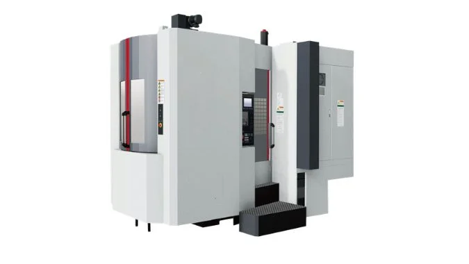
A vertical-horizontal machining center—also known as a universal or five-face machining center—combines vertical and horizontal milling, drilling, boring, and tapping on a single CNC platform. By automatically reorienting the spindle or worktable, it machines the top and four side surfaces in a single setup, drastically reducing clamping errors, fixtures, and cycle times1 for complex multi-sided parts.
What Is the Structure of a Vertical-Horizontal Machining Center?
A complex machine structure can appear difficult to understand. Without knowing its main parts, buyers may select unsuitable specifications or underestimate maintenance needs.
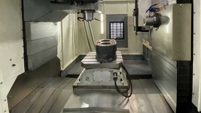
Vertical-horizontal machining center integrates two independent spindle units—one dedicated vertical and one dedicated horizontal—on a single, high-rigidity cast-iron machine bed. Built around a central CNC rotary table, this dual-spindle structure allows direct, sequential switching between vertical top-machining and horizontal side-machining on the clamped workpiece without secondary setup.
Main Structural Components
The foundation of the machine is a heavy-duty, high-strength cast-iron bed engineered with internal ribbing to absorb cutting vibrations2 and eliminate dynamic deformation during heavy milling.
Mounted on this shared bed is a dual-column layout featuring an "A-frame" column design, which provides superior torsional and bending stiffness. Rather than using an articulated tilting head, the system integrates two dedicated, independent spindles:
- Vertical Spindle Unit: Mounted on the vertical column for top-face milling, drilling, and tapping.
- Horizontal Spindle Unit: Mounted adjacent to the table for deep boring and four-side milling.
- Integrated Drive & Guideways: The X-axis drive mount and end support are cast integrally with the saddle to maximize transmission rigidity, supported across all axes by heavy-duty roller linear guideways.
How the Dual-Spindle Structure Supports Five-Sided Machining
Machining all five exposed faces in a single setup relies on the coordination between the central CNC rotary table and the independent dual-spindle layout:
- Top-Surface Operations: The dedicated vertical spindle descends to machine the top plane, pockets, and vertical mounting holes.
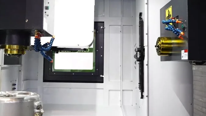
- Four-Side Operations: The horizontal spindle engages the workpiece from the side, while the central rotary table indexes through 360 degrees to present each of the four side faces consecutively.
Because both spindles operate with dedicated, fixed orientations rather than an indexing pivot head, the machine avoids the mechanical backlash, clamping deflection, and angular positioning wear common in universal tilting heads. This rigid dual-station architecture drastically reduces manual handling, preserves unified datum references, and delivers maximum cutting stability across all five surfaces.
What Level of Precision Can a Vertical-Horizontal Machining Center Achieve?
Small positioning errors can ruin an expensive complex part. Repeated clamping makes this problem worse because every new setup can introduce another reference error.
A well-configured vertical-horizontal machining center may achieve positioning accuracy of about 0.01 mm and repeat positioning accuracy of about 0.008 mm. A precision rotary table may provide indexing accuracy near ±2 arc seconds, although actual results depend on the machine, environment, tooling, and process.
Typical Accuracy Indicators
Positioning accuracy shows how closely an axis reaches its programmed location. Repeat positioning accuracy shows how consistently the axis returns to that same location. Both values matter, but they describe different aspects of machine performance.
Rotary table accuracy is also important. A small angular error can create a larger dimensional error at the edge of a wide workpiece. Precision encoders and reliable table clamping help control this problem.
| Accuracy Item | Typical Reference Value | What It Indicates |
|---|---|---|
| Linear positioning accuracy | About 0.01 mm | Accuracy of commanded axis movement |
| Linear repeat positioning accuracy | About 0.008 mm | Consistency of repeated axis movement |
| Rotary table indexing accuracy | About ±2 arc seconds | Accuracy of the commanded table angle |
| Rotary repeat indexing accuracy | About ±2 arc seconds | Consistency when returning to an angle |
These figures are reference values rather than a guarantee for every machine. Some high-grade models can achieve tighter tolerances. Basic models may provide lower accuracy. The machine specification should always state the measurement standard and test conditions.
Factors That Affect Actual Part Accuracy
The final part tolerance does not depend on the machine specification alone. Temperature changes can expand the machine structure and workpiece3. Tool wear can change the cutting diameter. A weak fixture can allow the part to move. Poor tool balance can cause vibration and reduce surface quality.
The CNC system can use error compensation to improve axis control4. Glass scales and high-resolution encoders can also support more stable positioning. Even so, the cutting process must match the machine’s capability.
One-clamping machining provides another accuracy advantage. Repeated setups can change the relationship between holes, surfaces, and datum points. A vertical-horizontal machining center keeps more features within one coordinate system. This setup can improve positional relationships even when the basic machine tolerance remains unchanged.
Routine calibration is still necessary. Ball-bar testing, laser measurement, spindle inspection, and rotary-axis checks5 can reveal wear before it causes rejected parts. Stable foundations and controlled workshop temperatures also help the machine maintain precision over time.
Does Using a Vertical-Horizontal Machining Center Reduce the Equipment’s Footprint?
Factory space is expensive, and separate machines need more than their own floor area. They also require aisles, service access, chip systems, and loading zones.
A vertical-horizontal machining center can reduce total floor use when it replaces both a vertical and a horizontal machining center. Its individual footprint is not small, but one combined machine may use about 30% to 50% less total space than two separate machines, including support areas.
Single-Machine Size Versus Total Production Space
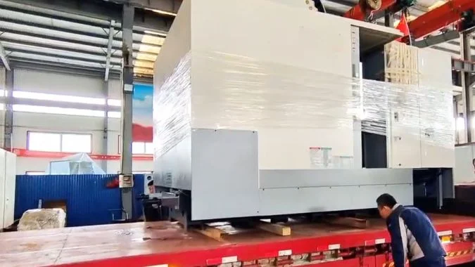
A vertical-horizontal machining center is usually larger than a vertical machining center with a similar work capacity. The combined machine needs room for its rotary mechanism, tool magazine, guarding, chip conveyor, and multi-direction movement. Its footprint may approach or slightly exceed that of a horizontal machining center in the same general size range.
The correct comparison is not always one combined machine against one single-purpose machine. A factory may need both vertical and horizontal functions. In that case, the practical comparison is one vertical-horizontal center against one vertical center plus one horizontal center.
| Equipment Arrangement | Relative Floor Requirement | Suitable Production Need |
|---|---|---|
| One standard VMC | Low | Mainly top-surface and plate machining |
| One standard HMC | Medium to high | Mainly side and box-part machining |
| One VMC plus one HMC | Highest | Separate vertical and horizontal processes |
| One vertical-horizontal center | Medium to high | Frequent multi-sided machining in one setup |
A combined machine can remove the aisle between two machines. It can also reduce the need for separate chip conveyors, coolant units, loading stations, and tool storage areas. These changes explain why total space savings may reach about 30% to 50%. The actual percentage depends on the machine layouts and local safety rules.
When the Space Advantage Applies
The footprint advantage only exists when the production process needs both machining directions. A workshop that only produces flat plates may gain more value from a compact vertical machining center. A plant that only machines box parts in high volume may prefer a dedicated horizontal machining center.
A vertical-horizontal machine offers stronger space efficiency when parts frequently move between vertical and horizontal operations. It also reduces work-in-process storage because parts do not wait between two separate machines. Material handling routes become shorter, and fewer fixtures may be needed.
The machine still requires enough service clearance. Operators need safe access to the table, tool magazine, coolant tank, and electrical cabinet. The purchase plan should therefore consider the full installation area rather than the machine dimensions shown in a catalog.
What Industries Require the Use of Vertical-Horizontal Machining Centers?
Complex parts often have tight tolerances and features on several faces. Separate operations can slow production and create errors between connected surfaces.
Vertical-horizontal machining centers are mainly used in automotive, aerospace, precision machinery, mold, energy, and general engineering production. They are most useful for complex parts that require accurate holes, pockets, planes, and angled features on several surfaces.
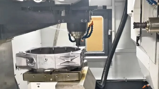
Automotive Manufacturing
Automotive production includes engine parts, transmission housings, suspension components, battery enclosures6, and special vehicle parts. Many of these components have holes and machined surfaces on several sides.
A vertical-horizontal machining center can complete several processes after one clamping. The tool magazine can hold drills, end mills, taps, boring tools, and face mills. The CNC system can select each tool automatically. This process reduces manual work and supports more consistent production.
The machine is especially useful for low-volume and medium-volume automotive parts with complex designs. Dedicated transfer lines may remain more efficient for extremely high production volumes.
Aerospace and Precision Machinery
Aerospace parts often use aluminum, titanium, stainless steel, and heat-resistant alloys7. These materials require stable cutting conditions. Aerospace components also have strict requirements for dimensional accuracy, feature position, and surface quality.
The rigid structure of a vertical-horizontal center supports heavy and precise cutting. Multi-axis control also allows the machine to reach difficult surfaces. Fewer setups can protect the relationship between critical features.
Precision machinery manufacturers use these machines for housings, valve bodies, robotic parts, instrument components, and production equipment. The equipment supports both prototype work and repeat production.
Mold and General Industrial Production
Mold manufacturing requires accurate cavities, flat reference surfaces, cooling channels, and side features. A combined machining center can process the main cavity and several side surfaces without moving the mold base to another machine. This approach can shorten the production cycle and reduce alignment work.
| Industry | Typical Parts | Main Benefit |
|---|---|---|
| Automotive | Gearbox housings, engine parts, brackets | Faster multi-process production |
| Aerospace | Structural parts, housings, precision frames | Stable accuracy and fewer setups |
| Precision machinery | Valve bodies, robotic parts, instrument housings | Better feature relationships |
| Mold manufacturing | Mold bases, cavities, side holes | Shorter setup and alignment time |
| Energy equipment | Pump bodies, turbine parts, manifolds | Flexible machining of large parts |
| General engineering | Frames, fixtures, custom components | Broad process capability |
The machine can also reduce manual intervention. The CNC controller manages axis movement, spindle speed, tool changes, and table indexing. Automation can lower labor demand and limit handling mistakes. Skilled staff are still required for programming, fixture planning, tool selection, inspection, and maintenance.
The main disadvantages also need attention. A vertical-horizontal machining center has a higher purchase cost than many single-function machines. Its structure is more difficult to maintain. Programming can be more demanding, and collision risks can increase when the table and spindle move through several positions. A suitable machine therefore needs strong technical support, clear operator training, dependable spare parts, and a process that can use its full capability.
Conclusion
A vertical-horizontal machining center combines multi-sided cutting, high precision, fewer setups, and efficient space use, making it valuable for complex parts across demanding manufacturing industries.
-
"The Benefits of 5-Axis CNC Machining", https://www.methodsmachine.com/blog/benefits-of-5-axis-machining/. Single-setup machining eliminates re-clamping errors by maintaining consistent datum references throughout operations, reducing cumulative positioning error and improving feature-to-feature accuracy, as demonstrated in precision manufacturing research on multi-axis machining strategies. Evidence role: mechanism; source type: paper. Supports: error reduction mechanisms in single-setup multi-sided machining. Scope note: Actual improvements depend on part geometry, fixture design, and machine capability ↩
-
"Pipe vibration attenuation through internal damping and …", https://pmc.ncbi.nlm.nih.gov/articles/PMC10119187/. Cast iron provides superior vibration damping compared to welded steel structures due to its graphite flake microstructure, and internal ribbing patterns enhance dynamic stiffness by increasing the moment of inertia while maintaining material efficiency, according to machine tool design research. Evidence role: mechanism; source type: research. Supports: vibration damping mechanisms in cast-iron machine tool structures. ↩
-
"Identification of a Workpiece Temperature Compensation …", https://pmc.ncbi.nlm.nih.gov/articles/PMC9741256/. Thermal expansion of machine tool structures and workpieces can account for 40-70% of total positioning error in precision machining operations, with temperature variations causing predictable linear expansion that requires compensation through environmental control or real-time correction systems. Evidence role: mechanism; source type: paper. Supports: thermal effects on dimensional accuracy in precision machining. ↩
-
"Roll, Pitch and Yaw Errors in CNC Milling Machine Tools", https://www.academia.edu/49581493/Roll_Pitch_and_Yaw_Errors_in_CNC_Milling_Machine_Tools. Modern CNC controllers implement software-based error compensation for geometric errors (pitch, yaw, straightness, squareness) and thermal drift by applying correction values derived from calibration measurements to commanded positions, achieving significant improvements in volumetric accuracy without mechanical modifications. Evidence role: mechanism; source type: paper. Supports: error compensation techniques in CNC machine tool control. Scope note: Effectiveness requires accurate error mapping and assumes repeatable error patterns ↩
-
"Resources: Calibration Procedures", https://www.nist.gov/pml/owm/laboratory-metrology/documentary-standards-and-resources/calibration-procedures. Ball-bar testing per ISO 230-4 and laser interferometry per ISO 230-2 constitute standard methods for evaluating geometric and positioning accuracy of CNC machine tools, enabling detection of axis errors, thermal drift, and mechanical wear before they exceed tolerance limits. Evidence role: general_support; source type: institution. Supports: standardized calibration methods for CNC machine tool accuracy verification. ↩
-
"Transmission Housing Machining – Trace-A-Matic", https://www.traceamatic.com/cnc-products/transmission-housings.html. Transmission housings and engine blocks require machining of mounting surfaces, bearing bores, and bolt holes on multiple faces with strict positional tolerances, making them suitable candidates for multi-sided machining strategies that maintain datum consistency, as described in automotive manufacturing process documentation. Evidence role: case_reference; source type: education. Supports: automotive components requiring multi-sided machining operations. ↩
-
"Titanium alloys", https://en.wikipedia.org/wiki/Titanium_alloys. Aerospace structural components commonly utilize aluminum alloys (7075, 2024), titanium alloys (Ti-6Al-4V), and nickel-based superalloys due to their strength-to-weight ratios and high-temperature performance, though these materials present machining challenges including low thermal conductivity and work hardening that require rigid machine tools and controlled cutting parameters. Evidence role: general_support; source type: education. Supports: common aerospace materials and their machining characteristics. ↩

Chris Lu
Leveraging over a decade of hands-on experience in the machine tool industry, particularly with CNC machines, I'm here to help. Whether you have questions sparked by this post, need guidance on selecting the right equipment (CNC or conventional), are exploring custom machine solutions, or are ready to discuss a purchase, don't hesitate to CONTACT Me. Let's find the perfect machine tool for your needs.