

Warum ist eine B-Achsen-Langdrehmaschine für die Herstellung komplexer medizinischer Knochenschrauben und Implantate unerlässlich?
Kleine medizinische Implantate lassen kaum Spielraum für Bearbeitungsfehler. Mehrfache Setups können zu Maßabweichungen, Oberflächenschäden, Gratbildung, Kontamination und kostspieligen Produktionsverzögerungen führen.
Eine Langdrehmaschine mit B-Achse fertigt winklige Bohrungen, Antriebsschlitze, Gewinde, gekrümmte Oberflächen und mehrere Seiten in einer einzigen Aufspannung. Sie stützt schlanke Teile in der Nähe des Schnittpunkts ab, reduziert Einrichtungsfehler und kann unter validierten Bearbeitungsbedingungen Serientoleranzen von nahezu ±0,003 mm einhalten.
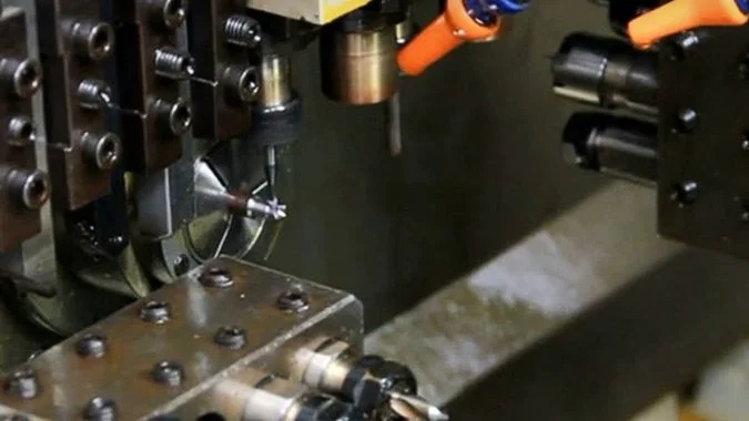
Medizinische Knochenschrauben können kürzer als 10 mm sein und Merkmale im 1-mm-Bereich aufweisen.1. Ihre geringe Größe macht sie nicht einfach in der Fertigung. Torx-Aussparungen, Sicherungsbohrungen, variable Gewinde und dünne Querschnitte schaffen anspruchsvolle Bearbeitungsbedingungen.2. Eine B-Achse bietet die für die Zusammenführung dieser Arbeitsgänge auf einer Plattform erforderliche Winkelsteuerung. Diese Prozessintegration wirkt sich direkt auf Genauigkeit, Zykluszeit, Oberflächenqualität und Teilehandling aus.
Was ist die Funktion der B-Achse bei einer Langdrehmaschine?
Standarddrehen kann winklige oder gekrümmte Konturen nicht ohne Weiteres erreichen. Ohne Winkelsteuerung erhöht jedes zusätzliche Setup das Fehlerrisiko, den Handlingaufwand und die Gefahr einer Beschädigung der fertigen Implantatoberfläche.
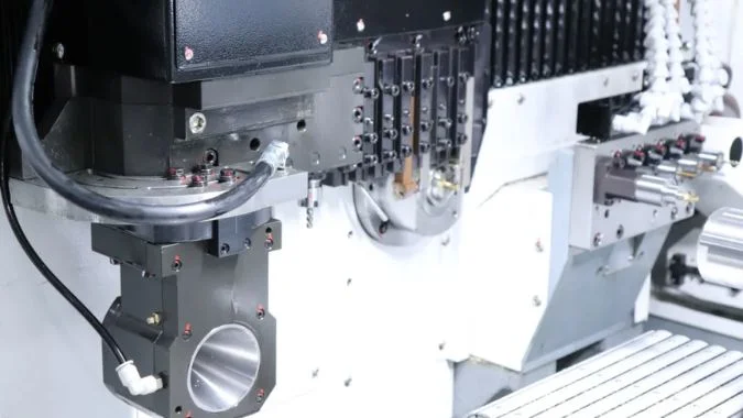
Die B-Achse dreht einen Werkzeugkopf oder eine Bearbeitungseinheit um eine winklige Mittellinie. Sie arbeitet mit den X-, Y- und Z-Achsen zusammen, um Schneidwerkzeuge in ausgewählten Winkeln zum Fräsen, Bohren, Gewindeschneiden, Nuten, Anfasen und für die Konturbearbeitung zu positionieren.
Wie erweitert die B-Achse die Bearbeitungsmöglichkeiten?
Die B-Achse verwandelt eine Langdrehmaschine von einer hauptsächlich drehbasierten Plattform in ein flexibles Dreh-Fräs-Bearbeitungszentrum. Ihr exakter Drehbereich hängt von der Maschinenkonstruktion ab. Einige Systeme bieten einen Bereich von beispielsweise 0–95°, während andere Konfigurationen etwa ±110° ermöglichen.3. Die Servosteuerung ermöglicht es der Achse, auf einen festgelegten Winkel zu indexieren oder sich mit anderen gesteuerten Achsen zu bewegen.
Diese Bewegung macht nicht-axiale Merkmale zugänglich, ohne das Werkstück zu entfernen. Eine medizinische Schraube kann in einem einzigen Zyklus mit einer winkligen Querbohrung, einer Torx-Aussparung, einer Fase und einer gefrästen Fläche versehen werden. Ein Dental-Abutment kann in derselben Aufspannung eine unregelmäßige Oberfläche, ein hexagonales Verriegelungsmerkmal und eine Führungshohlung mit mehreren Winkeln erhalten.
Die mitlaufende Führungshülse stützt das Stangenmaterial zudem nahe am Schnittpunkt ab. Diese Struktur ist bei der Bearbeitung von Titan oder biologisch abbaubarem Material mit Durchmessern von etwa 0,5–2 mm nützlich.4. Sie reduziert Biegung und Vibration, während die B-Achse die Werkzeugausrichtung steuert.5.
| B-Achsen-Fähigkeit | Einsatz in der Medizintechnik | Hauptfertigungsvorteil |
|---|---|---|
| Winkeleinstellung | Winkelbohrungen und Arretierfunktionen | Weniger Rüstvorgänge |
| Mehrachsige Bewegung | Gekrümmte Oberflächen und schraubenförmige Nuten | Flüssigere Konturübergänge |
| Werkzeugwinkelsteuerung | Fasen und Kantenbearbeitung | Geringerer Bedarf an manuellem Entgraten |
| Dreh-Fräs-Integration | Gewinde, Abflachungen und Antriebsvertiefungen | Komplettbearbeitung in einer Aufspannung |
| Optimierte Schnittrichtung | Dünne Wände und Mikrostrukturen | Weniger Gratbildung und geringere Verformung |
Warum ist die Komplettbearbeitung in einer Aufspannung für Implantate wichtig?
Jeder neue Spannvorgang führt zu einer weiteren Bezugspunktverschiebung6. Selbst ein geringer Positionierungsunterschied kann das Verhältnis zwischen Schraubengewinde, Antriebsaussparung und Sicherungsbohrung beeinflussen. Eine B-Achse hält diese Merkmale an derselben Bearbeitungsreferenz fest.
Wiederholtes Handling kann zudem eine fertige Oberfläche beschädigen. Es kann zu Spannstellen führen oder vor der Reinigung und Passivierung Partikel hinterlassen. Die Fertigung mit nur einer Aufspannung macht einen validierten Reinigungsprozess nicht überflüssig. Sie reduziert jedoch unnötige Kontakte und Prozessbewegungen. Diese Reduzierung ist wertvoll für Teile mit strengen Anforderungen an die Oberflächenintegrität und Rückverfolgbarkeit.
Der Schneidwinkel kann ebenfalls angepasst werden für Titanlegierungen, Kobalt-Chrom-Legierungen, Edelstahl und neuere biologisch abbaubare Materialien7. Ein besserer Werkzeugansatz kann die Gratbildung und Eigenspannungen an dünnen Wänden reduzieren. Diese Bedingungen können bei ordnungsgemäß kontrolliertem Fertigungsprozess eine bessere Ermüdungsbeständigkeit unterstützen.
Kann die B-Achse Bearbeitungen sowohl an der Hauptspindel als auch an der Gegenspindel durchführen?
Eine schlechte Spindelkoordination kann dazu führen, dass eine Seite der Maschine stillsteht. Sie kann zudem zu Unklarheiten darüber führen, ob eine B-Achse zwei separate Werkstücke gleichzeitig bearbeiten kann.
Eine B-Achse kann so konfiguriert sein, dass sie die Hauptspindel, die Gegenspindel oder beide Bearbeitungszonen zu unterschiedlichen Zeiten bedient. Eine physische B-Achse kann jedoch normalerweise nicht an beiden Spindeln gleichzeitig separate Teile schneiden. Das Maschinenlayout und der Zugang zum Werkzeugmagazin bestimmen ihre tatsächliche Reichweite.
Wie arbeiten Haupt- und Gegenspindel zusammen?
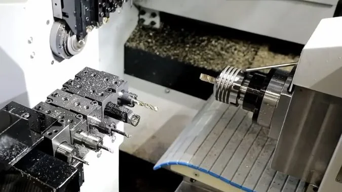
Ein Langdrehautomat mit zwei Spindeln verwendet häufig unabhängige CNC-Kanäle. Die Hauptspindel führt die Vorderseitenbearbeitung durch, während die Gegenspindel das Teil übernimmt und die Rückseitenbearbeitung abschließt. Nach der Übergabe kann die Hauptspindel mit der Bearbeitung des nächsten Stangenabschnitts beginnen, während die Gegenspindel das vorherige Teil fertigstellt. Diese parallele Struktur kann Leerlaufzeiten reduzieren.
Die B-Achse ist normalerweise auf einer definierten Werkzeugbank, einem Schlitten oder einer unabhängigen Werkzeugeinheit montiert. Ihre physische Position bestimmt, welche Spindel sie erreichen kann. Einige Maschinendesigns erlauben es, dass die B-Achsen-Werkzeuge beide Spindelpositionen anfahren können. Andere Designs legen sie hauptsächlich auf die Haupt- oder die Gegenspindel fest. Daher muss vor der Genehmigung eines Prozessplans eine Maschinenspezifikation überprüft werden.
Eine einzelne B-Achse nimmt zu jedem Zeitpunkt nur eine physische Bearbeitungsposition ein. Sie kann ein abgewinkeltes Merkmal an der Hauptspindel fräsen und später ein Merkmal auf der Rückseite an der Gegenspindel bearbeiten. Normalerweise kann sie nicht beide Schnitte gleichzeitig ausführen.
| Maschinenaktivität | Hauptspindel | Unterspindel | Rolle der B-Achse |
|---|---|---|---|
| Vorderseitenbearbeitung | Aktiv | Verfügbar oder in Betrieb | Kann Werkzeuge für abgewinkelte Merkmale positionieren |
| Teileübergabe | Synchronisierung | Synchronisierung | Normalerweise außerhalb des Übergabebereichs |
| Rückseitenbearbeitung | Startet das nächste Teil | Fertigstellung des vorherigen Teils | Kann den zugänglichen Spindelbereich bedienen |
| Parallele Produktion | Bearbeitet neues Stangenmaterial | Fertigstellung des übergebenen Bauteils | Führt jeweils einen erreichbaren Arbeitsgang aus |
Welche medizinischen Teile profitieren von der Doppelspindelfertigung?
Orthopädische Schrauben erfordern häufig eine vollständige Bearbeitung an beiden Enden. Die Hauptspindel kann das Gewindeprofil drehen, den Kopf formen und die Antriebsvertiefung fräsen. Die Gegenspindel kann das Bauteil vor dem Abstechen greifen und die Rückseite fertigstellen. Sie kann zudem bohren, plandrehen, anfasen oder Spitzenmerkmale fertigbearbeiten.
Dieser Prozess vermeidet es, ein nahezu fertiggestelltes Mikrobauteil zur späteren Neuzuführung in eine Ablage fallen zu lassen. Dies ist wichtig, da sehr kleine Schrauben schwer erneut auszurichten und einzuspannen sind. Ein zweiter Ladevorgang birgt zudem das Risiko von Kratzern, vermischten Chargen und Bezugsfehlern.
Zykluszeitgewinne hängen vom Ausgleich der Arbeitsgänge ab. Wenn die Rückseitenbearbeitung wesentlich länger dauert als die Vorderseitenbearbeitung, kann die Gegenspindel zum limitierenden Faktor werden. Die Prozessplanung sollte die Arbeitsgänge nach Möglichkeit verteilen. Gleichzeitiger Werkzeugeinsatz, Änderungen der Werkzeugwege und geeignete Schnittdaten können dieses Gleichgewicht verbessern. Unter den richtigen Bedingungen kann die integrierte Bearbeitung die Zykluszeit um mehr als 30% reduzieren, während bei einigen Teilen eine drei- bis fünffache Steigerung8 gegenüber einer fragmentierten Produktion auf mehreren Maschinen erzielt werden kann.
Wie macht die B-Achse teure, schrägstellbare angetriebene Werkzeugaufnahmen überflüssig?
Spezielle winklige angetriebene Werkzeuge erhöhen die Kosten, belegen Werkzeugplätze und bieten möglicherweise nicht die für Mikrostrukturen erforderliche Spindeldrehzahl. Sie führen zudem zu einem höheren Wartungs- und Einrichtungsaufwand.
Die B-Achse verringert die Abhängigkeit von winkligen angetriebenen Werkzeugaufnahmen, indem sie ein Standardwerkzeug oder eine externe Hochfrequenzspindel auf den erforderlichen Schnittwinkel dreht. Sie macht zwar nicht jedes angetriebene Werkzeug überflüssig, kann jedoch viele Arbeiten mit festem Winkel durch eine einfachere und kostengünstigere Einrichtung ersetzen.
Was ist die praktische Substitutionsmethode?
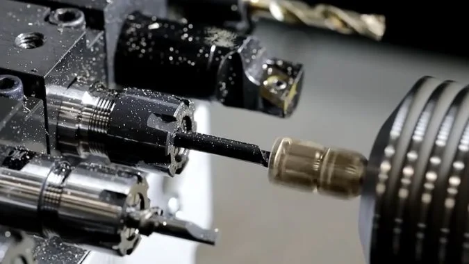
Die Grundidee ist einfach. Die B-Achse ermöglicht die Winkelpositionierung, während eine feststehende Hochgeschwindigkeitsspindel die Werkzeugrotation übernimmt. Die Spindel benötigt keinen eigenen servogesteuerten Winkelmechanismus, da die Maschinenachse den Anstellwinkel festlegt.
Eine Aufnahmeverlängerung kann eine unabhängige Hochfrequenz-Frässpindel aufnehmen. Eine typische Mikrobearbeitungsspindel kann mit 30.000–80.000 U/min laufen und einen Rundlauf von 1 μm oder weniger aufweisen9. Dieser Drehzahlbereich ist nützlich für kleine Fräser, die bei Torx-Schlitzen, schrägen Bohrungen, schmalen Nuten und Mikrokonturen eingesetzt werden.
Das CNC-Programm indexiert die B-Achse, startet die externe Spindel und koordiniert die Bewegung mit den Linearachsen. Diese Anordnung kann Werkzeugwechsel und manuelle Winkeleinstellungen reduzieren. Sie kann zudem andere Werkzeugplätze freimachen, wenn eine Spindel mehrere Winkelanstellungen abdeckt.
| Konfiguration | Winkelsteuerung | Typische Drehzahl | Optimale Verwendung |
|---|---|---|---|
| Feststehendes angetriebenes Werkzeug | Durch Haltergeometrie festgelegt | Niedrig bis mittel | Wiederholte Merkmale in einem Winkel |
| Servo-Winkel-angetriebenes Werkzeug | In die Werkzeugaufnahme integriert | Variabel | Flexible, hochwertige Bearbeitung |
| B-Achse mit Standardspindel | Durch die Maschinenachse bereitgestellt | Mittel bis hoch | Allgemeine Mehrwinkelbearbeitung |
| B-Achse mit Hochfrequenzspindel | Durch die Maschinenachse bereitgestellt | 30.000–80.000 U/min | Mikrolöcher, Schlitze und feine Konturen |
Wann ist ein angetriebenes Winkelwerkzeug noch notwendig?
Eine Hochfrequenzspindel ist hauptsächlich für leichte Zerspanungsarbeiten konzipiert. Aufgrund ihres kleinen Motors und der Werkzeugschnittstelle bietet sie möglicherweise nicht genügend Drehmoment für schweres Schruppen, große Bohrungen oder tiefe Nuten. Ihr verlängerter Überhang kann zudem die Steifigkeit verringern. Diese Einschränkungen werden bei harten Materialien und großen Schnitttiefen besonders relevant.
Ein integriertes B-Achsen-Angetriebenes Werkzeug bleibt nützlich, wenn ein Prozess hohes Drehmoment und kontinuierliche Mehrachsbewegungen erfordert. Komplexe Spiralfräsungen, tiefe Materialabtragungen und anspruchsvolle Bearbeitungen gekrümmter Oberflächen erfordern möglicherweise eine steifere Anordnung der angetriebenen Werkzeuge. Dabei müssen die Maschinenstruktur, das Spindellagerdesign, die Werkzeughalterlänge und die Schnittkräfte berücksichtigt werden.
Die B-Achse sollte daher eher als Mittel zur Verringerung der Abhängigkeit von kostspieligen Winkelköpfen betrachtet werden und nicht als universeller physischer Ersatz. Für indexierte Winkellochbohrungen, flache Nuten, Mehrseitenbearbeitung und viele medizinische Mikrostrukturen kann eine Standard- oder Hochfrequenzspindel eine kostengünstigere Lösung bieten. Für schweres Zerspanen bleibt eine steifere Anbindung oft notwendig.
Welche Präzision kann eine Langdrehmaschine mit B-Achsen-Funktionalität erreichen?
Spezifikationen im Mikrometerbereich können ohne stabile Werkzeugsysteme und Temperaturkontrolle irreführend sein. Die reine Maschinenspezifikation garantiert allein noch nicht die Endtoleranz eines medizinischen Implantats.
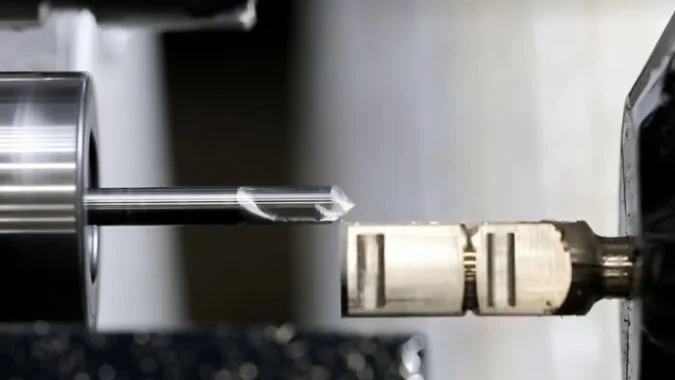
Eine leistungsfähige Langdrehmaschine mit B-Achse kann eine lineare Positioniergenauigkeit von ca. 0,003 mm und eine Wiederholgenauigkeit von ca. 0,001 mm erreichen. Die B-Achsen-Teilung kann 0,001° erreichen, während validierte Bauteiltoleranzen üblicherweise innerhalb von ±0,005 mm liegen und bei geeigneten Mikrobauteilen bis zu ±0,002–0,003 mm betragen können.
Welche Präzisionskennzahlen sind am wichtigsten?
Die Positioniergenauigkeit beschreibt, wie exakt eine Achse einen programmierten Punkt erreicht. Die Wiederholpositioniergenauigkeit beschreibt, wie konsistent sie zu diesem Punkt zurückkehrt. Beide Werte sind wichtig, entsprechen jedoch nicht der Genauigkeit des Fertigteils. Das Endergebnis hängt zudem von der Ausrichtung der Führungsbuchse, der Materialqualität, dem Spindelrundlauf, der Schnittkraft, dem Werkzeugverschleiß, dem Zustand des Kühlschmiermittels und der thermischen Stabilität ab.
Winkelfehler der B-Achse führen zudem zu größeren linearen Fehlern, je weiter der Schnittpunkt vom Achsmittelpunkt entfernt ist. Der Werkzeugüberhang muss daher kontrolliert bleiben. Ein kurzer und steifer Werkzeugaufbau unterstützt eine bessere Positionsgenauigkeit der Merkmale sowie eine höhere Oberflächengüte.
| Präzisionskennzahl | Typischer Hochleistungswert | Praktische Bedeutung |
|---|---|---|
| Positioniergenauigkeit der Linearachse | Etwa 0,003 mm | Fähigkeit, eine programmierte Position zu erreichen |
| Wiederholgenauigkeit der Linearachse | Etwa 0,001 mm | Fähigkeit, dieselbe Bewegung zu wiederholen |
| B-Achsen-Teilungsgenauigkeit | Etwa 0,001° | Winkelpositionierung der Werkzeugeinheit |
| Wiederholgenauigkeit der B-Achse | Etwa ±0,0005° bis ±0,001° | Konsistenz bei wiederholter Indexierung |
| Stabile Chargentoleranz | Etwa ±0,005 mm | Gängiges Fertigungsziel unter Kontrolle |
| Hochpräzise Mikrobauteiltoleranz | Etwa ±0,002–0,003 mm | Möglich mit einem fähigen und validierten Prozess |
Wie lässt sich ±0,003 mm in der Produktion einhalten?
Stabile Bearbeitung im Mikrometerbereich erfordert mehr als nur den Kauf einer Maschine mit geeigneter Spezifikation. Das Stangenmaterial muss hinsichtlich Durchmesser, Geradheit und Materialzustand kontrolliert sein. Die Führungsbuchse muss auf die Stange abgestimmt sein und Unterstützung ohne übermäßige Reibung bieten. Die Schneidwerkzeuge müssen einen geringen Rundlauffehler und ein berechenbares Verschleißverhalten aufweisen.
Auch die Temperatur beeinflusst das Ergebnis. Maschinenaufwärmzeiten, Kühlschmierstoffkontrolle und Hallentemperatur reduzieren thermisch bedingte Bewegungen. Die Grenzen der Standzeit sollten auf gemessener Merkmalsdrift basieren, anstatt auf sichtbarem Werkzeugausfall. In-Prozess-Messtaster oder regelmäßige Inspektionen können Abweichungen erkennen, bevor eine Charge die Toleranz überschreitet.
Medizintechnikhersteller müssen zudem die Gratkontrolle, Reinigung, Oberflächengüte und Rückverfolgbarkeit validieren.10. Die Maßhaltigkeit allein beweist nicht, dass ein Implantat akzeptabel ist. Der Prozess sollte geeignete Inspektionsmethoden, kalibrierte Ausrüstung, kontrollierte Handhabung und dokumentierte Qualitätsprüfungen umfassen.
Schlussfolgerung
Ein B-Achsen-Langdrehautomat kombiniert Winkelbearbeitung, Führungsbuchsenunterstützung, Doppelspindelfertigung und Komplettbearbeitung in einer Aufspannung, um komplexe medizinische Implantate mit hoher Präzision, Konsistenz und geringerem Handhabungsrisiko herzustellen.
-
"Orthopädische Hardware und Ausrüstung für Anfänger. Teil 2", https://pmc.ncbi.nlm.nih.gov/articles/PMC3215475/. Literatur zu orthopädischen Implantaten belegt, dass Knochenschrauben für kleine Fragmente und Minifragmente einen Durchmesser von ca. 1,5 mm bis 4,0 mm bei Gesamtlängen von üblicherweise 4 mm bis 30 mm aufweisen. Dies erfordert eine Präzision im Submillimeterbereich bei Gewindeprofilen, Antriebsaussparungen und Verriegelungselementen. Belegrolle: allgemeine Unterstützung; Quellentyp: Bildung. Unterstützt: Größenbereiche kleiner medizinischer Knochenschrauben für orthopädische Anwendungen. ↩
-
"6 Herausforderungen der Präzisionsbearbeitung GELÖST mit Smart DFM", https://www.phi2.com/blog/6-precision-machining-challenges-solved-with-smart-dfm/. Die Fertigungsforschung zeigt, dass kleinteilige Merkmale wie Antriebsaussparungen, Querbohrungen und variable Gewindeformen bei medizinischen Implantaten Herausforderungen darstellen, darunter eingeschränkter Werkzeugzugang, Gratbildung, maßliche Abweichungen durch Schnittkräfte und Schwierigkeiten bei der Aufrechterhaltung der Oberflächenintegrität über mehrere Merkmalstypen hinweg in einem Werkstück. Belegrolle: Mechanismus; Quellentyp: Forschung. Unterstützt: technische Herausforderungen bei der Bearbeitung komplexer Mikrostrukturen in medizinischen Implantaten. ↩
-
"Langdrehautomat | CNC-Maschinen New York", https://starcnc.com/products/. Industriestandards für Werkzeugmaschinen zeigen, dass Drehachsen-B-Konfigurationen üblicherweise von begrenzten Indexiersystemen (±30° bis ±45°) bis hin zu voll rotationsfähigen Konstruktionen reichen, wobei Implementierungen für kontinuierliche Bearbeitung je nach Maschinenarchitektur und Anforderungen an die Kollisionsvermeidung typischerweise einen Winkelbereich von ±90° bis ±120° bieten. Nachweisrolle: Statistik; Quellentyp: Institution. Unterstützt: Typische Winkelbewegungsbereiche für Drehachsen in Präzisions-CNC-Maschinen. Anmerkung: Der tatsächliche Bereich variiert erheblich je nach Hersteller und Maschinenmodell. ↩
-
"Vibrationsunterdrückung durch den Einsatz von Input-Shaping-Regelung in …", https://pmc.ncbi.nlm.nih.gov/articles/PMC8951330/. Die Forschung zur Zerspanungsmechanik zeigt, dass eine nahe an der Schnittzone positionierte Führungshülsenabstützung die Werkstückdurchbiegung und Vibrationen signifikant reduziert. Dies ist besonders wichtig bei schlanken Teilen mit einem Längen-Durchmesser-Verhältnis von mehr als 3:1, bei denen eine ungestützte Bearbeitung zu Maßfehlern, Rattern und schlechter Oberflächengüte führen kann. Nachweisrolle: Mechanismus; Quellentyp: Forschung. Unterstützt: Das mechanische Prinzip der Führungshülsenabstützung zur Reduzierung der Werkstückdurchbiegung bei der Bearbeitung kleiner Durchmesser. ↩
-
"Durchbiegung und Präzision beim CNC-Langdrehen", https://metalcutting.com/knowledge-center/deflection-precision-cnc-swiss-machining/. Die Forschung zur Dynamik von Werkzeugmaschinen zeigt, dass Stützstrukturen in der Nähe der Schnittzone die effektive freie Länge schlanker Werkstücke reduzieren, wodurch die Eigenfrequenz und Steifigkeit des Werkstück-Maschinen-Systems erhöht werden, was die Durchbiegung unter Schnittkräften signifikant verringert und regenerative Rattervibrationen unterdrückt. Nachweisrolle: Mechanismus; Quellentyp: Forschung. Unterstützt: Das mechanische Prinzip, durch das die Führungshülsenabstützung Durchbiegung und Vibrationen bei schlanken Werkstücken reduziert. ↩
-
"Bezugselement in GD&T: Definition, Merkmale und Typen …", https://www.xometry.com/resources/machining/datum-in-gd-t/. Prinzipien der Fertigungstechnik belegen, dass jede Werkstückumspannung potenzielle Bezugsfehler durch Vorrichtungstoleranzen, Spannvariationen und Ausrichtungsunsicherheiten einführt, wobei die Fehlerakkumulation besonders bei Anwendungen mit engen Toleranzen, bei denen Merkmalsbeziehungen im Mikrometerbereich eingehalten werden müssen, signifikant wird. Nachweisrolle: Mechanismus; Quellentyp: Bildung. Unterstützt: Das Prinzip der Bezugsübertragung und Fehlerakkumulation in der Fertigung mit mehreren Aufspannungen. ↩
-
"Sicherheit von Metallen und anderen Materialien in medizinischen Anwendungen …", https://www.fda.gov/medical-devices/products-and-medical-procedures/safety-metals-and-other-materials-used-medical-devices. Die Literatur zur Materialwissenschaft medizinischer Geräte identifiziert Titanlegierungen (insbesondere Ti-6Al-4V), Kobalt-Chrom-Legierungen, Edelstahl (316L) sowie biologisch abbaubare Polymere und Magnesiumlegierungen als Hauptmaterialkategorien für orthopädische und dentale Implantate, die aufgrund ihrer Biokompatibilität, mechanischen Eigenschaften, Korrosionsbeständigkeit und spezifischen klinischen Anwendungen ausgewählt werden. Nachweisrolle: allgemeine Unterstützung; Quellentyp: Bildung. Unterstützt: Häufig verwendete Materialkategorien bei der Herstellung medizinischer Implantate. ↩
-
"Effiziente Zeitplanung zur Reduzierung von Rüstzeiten und Steigerung …", https://dspace.mit.edu/entities/publication/76066a30-586f-4948-9df9-9c7499a3e196. Studien zur Fertigungseffizienz zeigen, dass die Zusammenlegung von Prozessen mit mehreren Aufspannungen zu Ein-Aufspannungs-Verfahren typischerweise Zykluszeitverkürzungen von 20–40 % bringt, wobei in Fällen, in denen das Teilehandling, die Komplexität der Vorrichtungen und die Rüstzeit erhebliche Anteile des ursprünglichen Produktionszyklus ausmachen, größere Verbesserungen (2–5-fache Produktivitätsgewinne) beobachtet werden. Nachweisrolle: Statistik; Quellentyp: Forschung. Unterstützt: Produktivitätsgewinne durch die Reduzierung von Rüstvorgängen in der Präzisionsfertigung. Anmerkung: Die tatsächlichen Gewinne hängen stark von der Teilekomplexität, dem ursprünglichen Prozessdesign und dem Ausgleich der Arbeitsvorgänge ab. ↩
-
"(PDF) Eine Ultrahochgeschwindigkeitsspindel für das Mikrofräsen", https://www.academia.edu/20318396/An_Ultra_high_Speed_Spindle_for_Micro_milling. Die Fachliteratur zur Präzisionsbearbeitung belegt, dass hochfrequente Motorspindeln für Mikrobearbeitungsoperationen typischerweise im Bereich von 30.000 bis 100.000 U/min arbeiten, wobei Präzisionsgeräte durch hochpräzise Lagersysteme und ausgewuchtete Rotorgruppen einen axialen und radialen Rundlauffehler von unter 1–2 μm erreichen. Beweisrolle: Statistik; Quellentyp: Forschung. Unterstützt: Leistungsspezifikationen von Hochfrequenzspindeln, die in Mikrobearbeitungsanwendungen eingesetzt werden. ↩
-
"Prozessvalidierung: Allgemeine Grundsätze und Praktiken", https://www.fda.gov/files/drugs/published/Process-Validation–General-Principles-and-Practices.pdf. Vorschriften für Medizinprodukte, einschließlich der FDA Quality System Regulation (21 CFR 820) und ISO 13485, erfordern von Herstellern, Fertigungsprozesse durch dokumentierte Nachweise zu validieren, dass Verfahren konsistent Produkte erzeugen, die vorgegebene Spezifikationen erfüllen, einschließlich Maßhaltigkeit, Oberflächenbeschaffenheit, Sauberkeit und vollständiger Rückverfolgbarkeit während der gesamten Produktion. Beweisrolle: Expertenkonsens; Quellentyp: Regierung. Unterstützt: Regulatorische Anforderungen an die Prozessvalidierung in der Herstellung von Medizinprodukten. ↩

Chris Lu
Mit mehr als einem Jahrzehnt praktischer Erfahrung in der Werkzeugmaschinenindustrie, insbesondere mit CNC-Maschinen, stehe ich Ihnen gerne zur Verfügung. Ganz gleich, ob Sie Fragen haben, die durch diesen Beitrag ausgelöst wurden, ob Sie Beratung bei der Auswahl der richtigen Ausrüstung (CNC oder konventionell) benötigen, ob Sie kundenspezifische Maschinenlösungen erforschen oder ob Sie bereit sind, einen Kauf zu besprechen, zögern Sie nicht, mich zu kontaktieren. Lassen Sie uns gemeinsam die perfekte Werkzeugmaschine für Ihre Bedürfnisse finden.