

Warum eignet sich der Moving Beam GMC für die Massenproduktion von Aluminiumlegierungen?
Langsame Beschleunigung, instabile Genauigkeit und mangelhafte Spanabfuhr können die Produktionskosten für Aluminium erhöhen. Diese Probleme verschärfen sich, wenn eine Maschine Hunderte von Teilen bearbeitet.
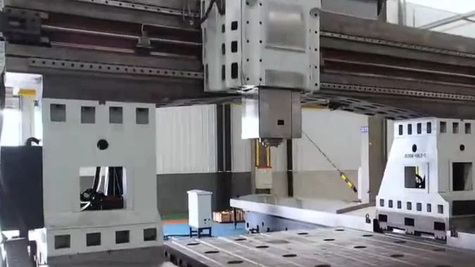
Ein Bearbeitungszentrum mit Fahrständer unterstützt die Aluminium-Massenproduktion durch geringe bewegte Masse, schnelle Beschleunigung, stabiles thermisches Verhalten, Integration von Hochgeschwindigkeitsspindeln und effiziente Spanabfuhr. Zudem sorgt der feststehende Tisch für eine gleichbleibende dynamische Leistung bei wechselndem Werkstückgewicht.
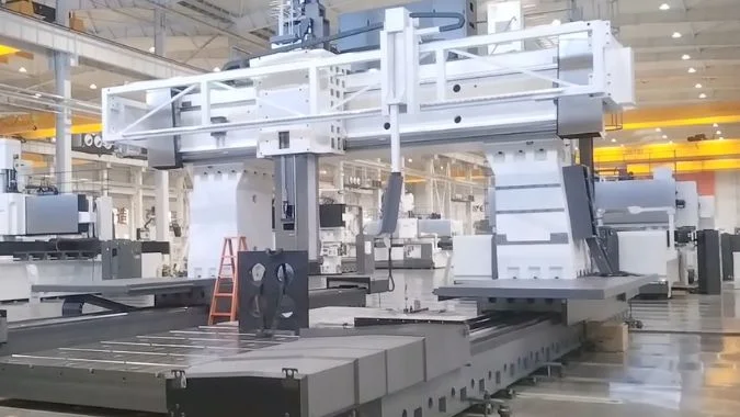
Die Aluminiumbearbeitung erscheint einfach, da die Schnittkräfte normalerweise gering sind.1. Doch die Massenproduktion stellt höhere Anforderungen. Die Maschine muss häufig die Richtung ändern, über lange Schichten hinweg die Genauigkeit beibehalten und große Mengen an Spänen abführen. Die folgenden strukturellen Faktoren zeigen, warum ein Fahrständer-Bearbeitungszentrum (GMC) diese Anforderungen erfüllen kann.
Warum ist die Fahrständerstruktur für schnelle Bewegungen besser geeignet als ein beweglicher Tisch?
Ein beweglicher Tisch muss jedes Kilogramm des Werkstücks bewegen. Diese sich ändernde Last verlangsamt die Beschleunigung, erhöht den Umkehrstoß und erschwert die Aufrechterhaltung stabiler Produktionseinstellungen.
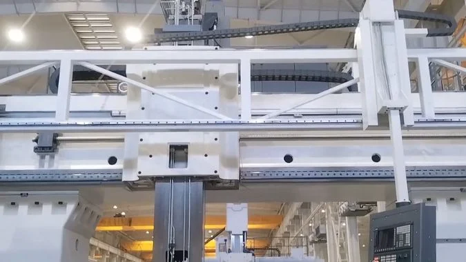
Eine Fahrständerkonstruktion bewegt eine leichtere und konstantere Masse, während Tisch und Werkstück feststehen. Die stabile Trägheit ermöglicht eine schnellere Beschleunigung, konsistentere Eilganggeschwindigkeiten, eine einfachere Servoeinstellung und geringere mechanische Belastungen bei häufigen Starts, Stopps und Richtungswechseln.
Konstante bewegte Masse verbessert die Bewegungssteuerung
Eine Maschine mit beweglichem Tisch muss Tisch, Vorrichtung und Werkstück gemeinsam beschleunigen. Die gesamte bewegte Masse ändert sich mit jedem Produktionsauftrag. Eine große Aluminiumplatte kann zudem ihren Schwerpunkt außerhalb der Antriebslinie haben. Dieser Zustand erzeugt eine größere Trägheitslast und kann bei schnellen Richtungswechseln ein Kippmoment verursachen.
Ein Fahrständer-Bearbeitungszentrum hält das Werkstück stationär. Das Antriebssystem bewegt stattdessen den Träger und die Spindeleinheit. Diese bewegte Masse bleibt von einer Charge zur nächsten nahezu konstant. Die Steuerung kann daher stabile Servoparameter verwenden, ohne große Anpassungen an das jeweilige Werkstückgewicht vornehmen zu müssen.
| Bewegungsfaktor | Fahrständer-Bearbeitungszentrum | Tisch-Bearbeitungszentrum |
|---|---|---|
| Bewegte Last | Leicht und nahezu konstant | Schwer und abhängig vom Werkstück |
| Beschleunigung | Hoch und wiederholbar | Begrenzt durch die maximal erwartete Last |
| Eilgang | Konsistent über verschiedene Aufträge hinweg | Oft reduziert für schwere Bauteile |
| Umkehrstoß | Unter | Höher |
| Platzbedarf in der Fertigung | Kompakter für lange Werkstücke | Zusätzlicher Platz für den Tischweg erforderlich |
Stabile Beschleunigung verkürzt Nebenzeiten
Massenproduktion umfasst viele Positionierbewegungen. Werkzeugwechsel, Lochbilder, Taschen und getrennte Merkmale erzeugen wiederholte Leerfahrten. Eine kleine Einsparung bei jeder Bewegung summiert sich bei hunderten von Teilen zu einer großen Ersparnis.
Der bewegliche Balken folgt der physikalischen Regel, schwere Objekte in Ruhe zu lassen und leichtere Teile zu bewegen2. Eine geringere Trägheitskraft reduziert die Belastung von Führungen, Schrauben, Kupplungen und Servomotoren. Beidseitig synchronisierte Antriebe können den Balken zudem steuern, ohne die durch hohe Trägheit bei der Umkehr verursachte Umkehrspielverstärkung. Diese Funktionen unterstützen Eilganggeschwindigkeiten, die auch dann stabil bleiben, wenn ein schwereres Werkstück in die Produktion gelangt.
Welchen Vorteil bietet eine reduzierte Achsträgheit für das Hochvorschub-Konturfräsen bei der Aluminium-Hochgeschwindigkeitsbearbeitung?
Komplexe Aluminiumkonturen enthalten Ecken, Bögen und kurze Werkzeugwegsegmente. Hohe Trägheit verursacht Nachlaufverzögerungen, Überschwingen, Oberflächenwellen und unerwünschte Eckenabrundungen bei hohen Vorschubgeschwindigkeiten3.
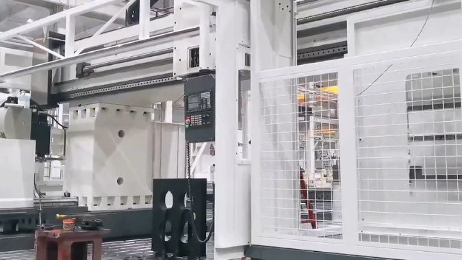
Eine reduzierte Achsträgheit ermöglicht dem Servosystem ein schnelleres Beschleunigen, Bremsen und Umkehren. Diese Reaktion verbessert die Konturnachführung, unterstützt höhere Regelverstärkungen, reduziert den Schleppfehler und schützt die Oberflächenqualität bei der Hochvorschubbearbeitung komplexer Aluminiumprofile.
Schnellere Reaktion schützt Konturgenauigkeit
Hochvorschub-Konturfräsen hängt nicht nur von der Spindeldrehzahl ab. Jede Linearachse muss zudem tausenden kleinen Befehlen folgen. Das Steuerungssystem ändert ständig die Achsgeschwindigkeit, wenn das Werkzeug in eine Ecke fährt, einem Bogen folgt oder sich über eine gekrümmte Oberfläche bewegt. Eine schwere Achse bewegt sich weiter, nachdem der Befehl zur Richtungsänderung gegeben wurde. Diese Bewegung erzeugt Verzögerungen4 und kann den Fräser vom programmierten Pfad abbringen.
Eine geringere bewegte Masse erfordert weniger Motordrehmoment für die gleiche Beschleunigung. Das Servo kann schneller reagieren und höhere Positions- und Geschwindigkeitsregelverstärkungen nutzen. Feedforward-Einstellungen werden ebenfalls effektiver, da das mechanische System mit weniger Verzögerung reagiert.
| Konturbearbeitungszustand | Auswirkung geringerer Trägheit |
|---|---|
| Scharfe Ecke | Schnelleres Bremsen reduziert Kurvenunterschnitt |
| Kleiner Bogen | Bessere Nachführung begrenzt Radiusfehler |
| Kurzes Liniensegment | Weniger Zeitverlust während der Beschleunigung |
| Richtungswechsel | Geringerer Stoß reduziert Vibrationen |
| Gekrümmte Oberfläche | Eine flüssigere Bewegung reduziert sichtbare Wellenbildung |
Hoher Vorschub wird nützlich, statt nur möglich
Aluminiumlegierungen erlauben oft Vorschubgeschwindigkeiten von 20–40 m/min oder mehr5 wenn Werkzeug, Spindelleistung und Maschinenkonfiguration dies zulassen. Ein hoher programmierter Vorschub hat jedoch wenig Wert, wenn die Steuerung an jeder Ecke abbremsen muss. Eine reduzierte Trägheit ermöglicht es den Achsen, mehr Zeit nahe dem befohlenen Vorschub zu verbringen.
Geringere Trägheitskräfte reduzieren zudem wechselnde Belastungen an Führungen und Getriebeteilen. Diese Reduzierung begrenzt die temporäre elastische Verformung während der Beschleunigung und Bremsung. Ein starrer Kastenbalken, eine optimierte Rippenanordnung und ein ausbalanciertes Doppelantriebssystem können das Steifigkeits-Masse-Verhältnis weiter verbessern. Linearmotoren oder massearme Kugelgewindetriebe können für ein direkteres Ansprechverhalten sorgen. Eine korrekte Servoeinstellung bleibt wichtig, da eine zu hohe Verstärkung dennoch Schwingungen erzeugen kann. Das mechanische Design und die Steuerungseinstellungen müssen als ein System zusammenarbeiten.
Warum ist die Integration einer elektrischen Hochgeschwindigkeitsspindel bei einer Fahrständerstruktur effektiver?
Eine hohe Spindeldrehzahl allein kann keine produktive Aluminiumbearbeitung garantieren. Eine schlecht abgestützte Spindel kann Wärme, Vibrationen, einen langen Überhang und ein verzögertes Achsansprechverhalten verursachen.
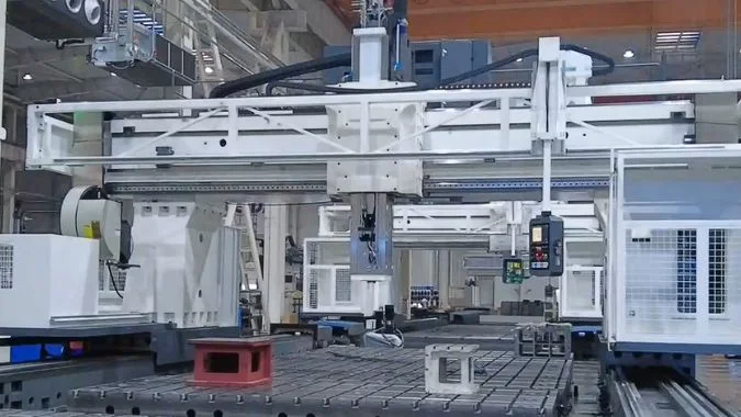
Eine bewegliche Balkenstruktur platziert die elektrische Spindel innerhalb einer leichten, starren und thermisch ausgeglichenen Baugruppe. Der kurze Spindelüberhang verbessert die Biegesteifigkeit, während die zentrierte Wärmequelle und die geringe bewegte Masse ein schnelles Ansprechverhalten, stabile Präzision und Hochgeschwindigkeitsschneiden unterstützen.
Kurzer Überhang erhöht die Rattergrenze
Hochgeschwindigkeitsfräsen von Aluminium verwendet oft eine geringe axiale Schnitttiefe, einen hohen Vorschub und eine hohe Spindeldrehzahl. Dieser Prozess erfordert eine starre Spindelverbindung, da selbst eine kleine Vibration Spuren an einer fertigen Wand oder einem Boden hinterlassen kann6.
Ein bewegliches Balkendesign kann den Spindelkopf direkt auf oder innerhalb des Balkens montieren. Der resultierende Stößelüberhang kann kurz bleiben. Ein kürzerer Hebelarm begrenzt das Biegen unter Schneid- und Beschleunigungslasten7. Die Struktur kann daher während des Hochgeschwindigkeitsfräsens eine höhere Rattergrenze beibehalten.
| Integrationspunkt | Produktionsvorteil |
|---|---|
| Kurzer Spindelüberhang | Höhere Biegesteifigkeit |
| Zentrierte Spindelposition | Ausgeglichene Belastung über den Balken |
| Elektrischer Spindelantrieb | Schnelles Ansprechen ohne lange Übertragungskette |
| Leichter Träger | Bessere Beschleunigung und geringerer Energieverbrauch |
| Symmetrische Abstützung | Vorhersehbareres thermisches Bewegungsverhalten |
Thermische Symmetrie unterstützt lange Produktionsläufe
Eine Elektrospindel erzeugt Wärme durch den Motor, die Lager und den Schneidprozess. Ungleichmäßige Wärme kann das Werkzeugzentrum verschieben und zu Maßabweichungen führen.8. Dieses Problem wird wichtig, wenn die Maschine über mehrere Schichten läuft.
Viele Maschinen mit beweglichem Träger verwenden einen symmetrischen Träger, zwei Stützen und beidseitige Antriebe. Die Spindel sitzt nahe am strukturellen Zentrum. Dieses Layout trägt dazu bei, die Wärme gleichmäßiger über die tragende Struktur zu verteilen. Thermische Ausdehnung kann dann hauptsächlich entlang einer vorhersehbaren Achse erfolgen, anstatt die X-Y-Geometrie zu verzerren. Spindelkühlung, Temperatursensoren und Kompensationssoftware können dieses Verhalten verbessern.
Die Kombination reduziert zudem unnötige Getriebeteile. Eine Hochgeschwindigkeits-Elektrospindel sorgt für eine direkte Drehreaktion, während der leichte Träger für eine schnelle lineare Reaktion sorgt. Spindeldrehzahlen von 10.000 bis 24.000 U/min können für viele Aluminiumanwendungen geeignet sein9, abhängig vom Werkzeugdurchmesser und dem erforderlichen Drehmoment. Das Gesamtsystem kann eine hohe Materialabtragsrate unterstützen, ohne allein von der Spindeldrehzahl abhängig zu sein.
Wie löst ein Fahrständer-Bearbeitungszentrum das Problem der Spanabfuhr bei großen Aluminiumvolumina?
Die Aluminiumbearbeitung erzeugt lange Späne, leichte Span-Nester und klebrige nasse Späne. Schwache Förderer und schmale Kanäle können schnell verstopfen, die Produktion stoppen und die Kühlschmierflüssigkeit verunreinigen.
Eine GMC mit beweglichem Träger bewältigt große Spanvolumina mit einem verbreiterten Scharnierbandförderer, einer Hochdruck-Spülung mit hohem Durchfluss, steilen Bettenentwässerungen und einer Fest-Flüssig-Trennung. Diese Systeme befördern sperrige, nicht magnetische Späne aus dem Arbeitsbereich und gewinnen gleichzeitig saubereres Kühlmittel zurück.
Der Förderer muss dem Verhalten von Aluminiumspänen entsprechen
Aluminiumspäne sind nicht magnetisch. Ein Magnetförderer kann diese nicht effektiv erfassen10. Ein standardmäßiger Schneckenförderer kann zudem lange Späne zu dichten Bündeln zusammenpressen. Diese Kompression kann zu Verstopfungen, Reibung und Hitze führen.
Ein Scharnierbandförderer bietet eine breite Transportfläche und eine hohe Tragfähigkeit11. Das Plattendesign kann lange, lockige oder blockförmige Späne transportieren, ohne auf Magnetismus angewiesen zu sein. Eine maßgeschneiderte Fördererbreite sollte der Breite der Maschinenführungen und dem vollständigen Arbeitsweg entsprechen. Diese Abdeckung verhindert, dass sich Späne außerhalb des Transportbereichs ansammeln.
| Komponente zur Spänekontrolle | Hauptfunktion |
|---|---|
| Verbreiterter Scharnierbandförderer | Transportiert große Mengen nichtmagnetischer Späne |
| Kühlmitteldüsen mit hohem Durchfluss | Drückt Späne in Richtung des Einlassbereichs |
| Hochdruckspülung | Zerschlägt Spänepakete und reinigt Abdeckungen |
| Schwingsieb | Trennt große Feststoffe vom Kühlmittel |
| Zyklonabscheider | Entfernt feinere Partikel aus der Flüssigkeit |
| Spanbrecher-Abstreifer | Verhindert, dass sich lange Späne um die Welle wickeln |
Die Bettgeometrie muss jeden Span leiten
Der feste Tisch erleichtert den Aufbau breiter Abflusswege um die Arbeitszone herum. Die Bettoberflächen sollten Neigungen von etwa 30 Grad oder mehr aufweisen, sofern es das Maschinendesign zulässt. Breite Kanäle sollten zu den Spanabfuhröffnungen führen. Glatte Abdeckungen sollten zudem Taschen beseitigen, in denen sich nasses Aluminium absetzen kann.
Hochstromdüsen in der Nähe des Werkzeugs bewegen die Späne, bevor sie ein Nest bilden können. Zusätzliche Düsen in der Nähe des Förderbandeinlasses verhindern Brückenbildungen. Pneumatisches Blasen kann helfen, wenn lange Profile verstreute Späne erzeugen, aber das Luftsystem darf die Späne nicht in Führungen oder elektrische Bereiche blasen.
Ein Schwingsieb oder Fliehkraftabscheider sollte das Kühlmittel vor der Rückführung aufbereiten. Eine frühzeitige Fest-Flüssig-Trennung senkt den Ölgehalt der ausgetragenen Späne und reduziert Schlamm im Kühlmitteltank. Große U-Nut-Aluminiumfräser können zudem kurze, kontrollierte Locken erzeugen und Aufbauschneiden reduzieren. Tägliche Kontrollen sollten Kettenspannung, Siebverstopfungen, Düsenausrichtung und angesammelten Schlamm umfassen. Aluminiumspezifische Schneidflüssigkeit kann Fleckenbildung, Korrosion und klebrige Spanablagerungen weiter reduzieren.
Schlussfolgerung
GMC-Maschinen mit beweglichem Balken kombinieren stabile Dynamik, präzises Hochgeschwindigkeits-Konturfräsen, effektive Spindelintegration und kontrollierte Spanabfuhr, was sie zu einer starken Plattform für die wiederholbare Aluminium-Massenproduktion macht.
-
"Der Einfluss der Bearbeitungsparameter von AW-7020 … – PMC", https://pmc.ncbi.nlm.nih.gov/articles/PMC12072895/. Forschung, die spezifische Schnittkräfte über verschiedene Metalle hinweg vergleicht, zeigt, dass Aluminiumlegierungen unter vergleichbaren Bearbeitungsbedingungen typischerweise 30-60 % geringere Schnittkräfte erfordern als Stahl, wobei die genauen Werte von der Legierungszusammensetzung und den Bearbeitungsparametern abhängen. Beweisrolle: Statistik; Quellentyp: Forschung. Unterstützt: Dass Aluminiumlegierungen bei Bearbeitungsvorgängen im Allgemeinen geringere Schnittkräfte erfordern als eisenhaltige Werkstoffe. Anmerkung zum Umfang: Ein direkter Vergleich ist begrenzt, da die Schnittkräfte je nach spezifischer Legierungssorte, Werkzeuggeometrie und Schnittbedingungen erheblich variieren. ↩
-
"Newtonsche Bewegungsgesetze | Glenn Research Center – NASA", https://www1.grc.nasa.gov/beginners-guide-to-aeronautics/newtons-laws-of-motion/. Newtons zweites Gesetz (F = ma) stellt fest, dass die Beschleunigung umgekehrt proportional zur Masse ist, wenn die Kraft konstant bleibt. Das bedeutet, dass Systeme, die leichtere Komponenten bewegen, mit der gleichen Motorkraft eine höhere Beschleunigung erreichen können. Beweisrolle: Mechanismus; Quellentyp: Enzyklopädie. Unterstützt: Dass eine Verringerung der bewegten Masse die Beschleunigung bei einer gegebenen aufgebrachten Kraft verbessert. ↩
-
"Kombinierte Konturfehler-Steuerungsmethode für Fünf-Achs-Maschinen …", https://pmc.ncbi.nlm.nih.gov/articles/PMC12098878/. Forschung zum Hochgeschwindigkeits-Konturfräsen zeigt, dass eine erhöhte Achsträgheit den Schleppfehler während der Beschleunigung und Verzögerung verstärkt, was zu Kantenverrundungen, Bahnüberschwingern und periodischen Oberflächenmarkierungen führt, wenn die Vorschubgeschwindigkeiten die dynamische Reaktionsfähigkeit des Systems überschreiten. Beweisrolle: Mechanismus; Quellentyp: Forschung. Unterstützt: Dass eine hohe bewegte Masse in CNC-Achsen bei Richtungswechseln mit hoher Geschwindigkeit zu Schleppfehlern, Überschwingern und Konturunungenauigkeiten führt. Anmerkung zum Umfang: Die Schwere dieser Effekte hängt von der Reglereinstellung, der Vorwärtskompensation und den Ruckbegrenzungen ab, nicht allein von der Trägheit. ↩
-
"Modellierung und Steuerung von Konturfehlern für Fünf-Achs-Maschinen …", https://research.engr.oregonstate.edu/mpcl/resources/5-Ax-CC1.pdf. Die Bewegungssteuerungsforschung zeigt, dass der Schleppfehler in Servosystemen proportional zur Lastträgheit zunimmt, da Achsen mit höherer Trägheit längere Einschwingzeiten erfordern und bei Richtungswechseln eine größere Phasenverzögerung aufweisen. Beweisrolle: Mechanismus; Quellentyp: Forschung. Unterstützt: Dass eine höhere bewegte Masse zu größeren Schleppfehlern und Reaktionsverzögerungen in servogesteuerten Achsen führt. Anmerkung zum Umfang: Der Zusammenhang kann teilweise durch Vorwärtssteuerung und höhere Regelschleifenverstärkungen kompensiert werden, wobei physische Trägheitsgrenzen bestehen bleiben. ↩
-
"Drehzahlen und Vorschübe", https://web.mae.ufl.edu/designlab/Advanced%20Manufacturing/Speeds%20and%20Feeds/Speeds%20and%20Feeds.htm. Die Literatur zur Hochgeschwindigkeitsbearbeitung berichtet von Vorschubgeschwindigkeiten für Aluminiumlegierungen im Bereich von 15-50 m/min in Produktionsumgebungen, wobei die spezifischen Werte von der Werkstückgeometrie, dem Werkzeugdurchmesser und der gewünschten Oberflächengüte abhängen. Beweisrolle: Statistik; Quellentyp: Forschung. Unterstützt: Dass moderne Aluminiumbearbeitungsvorgänge üblicherweise Vorschubgeschwindigkeiten im Bereich von 20-40 m/min oder höher einsetzen. Anmerkung zum Umfang: Erreichbare Vorschubgeschwindigkeiten variieren erheblich basierend auf Maschinensteifigkeit, Werkzeugqualität und spezifischer Legierungssorte. ↩
-
"Untersuchung der Faktoren, die Werkzeugvibration und Oberfläche beeinflussen …", https://pmc.ncbi.nlm.nih.gov/articles/PMC10223796/. Studien zur Bearbeitungsdynamik zeigen, dass Werkzeugvibrationen periodische Verschiebungsmuster auf die bearbeitete Oberfläche übertragen, was zu sichtbaren Rattermarken, erhöhter Oberflächenrauheit und Maßabweichungen führt. Beweisrolle: Mechanismus; Quellentyp: Forschung. Unterstützt: Dass Vibrationen und Rattern während Bearbeitungsvorgängen sichtbare Oberflächenunregelmäßigkeiten und erhöhte Rauheit erzeugen. ↩
-
"Rechner für einseitig überstehenden Balken — Einseitiger Überstand", https://www.firgelliauto.com/blogs/engineering-calculators/overhanging-beam-calculator-single-overhang?srsltid=AfmBOopr92hrP2U6dNXB0UA_BavbEIY1hMA56471dNcDjecNXhVPK6dK. Die Prinzipien der Balkenmechanik belegen, dass die Durchbiegung eines Auslegers mit der dritten Potenz der Überhanglänge zunimmt. Das bedeutet, dass kürzere Spindelausladungen bei identischen Schnittkräften eine wesentlich höhere Steifigkeit und eine geringere Verschiebung des Werkzeugpunkts bieten. Beweisrolle: Mechanismus; Quellentyp: Bildung. Unterstützt: dass die Reduzierung der Auslegerlänge die Biegesteifigkeit erhöht und die Durchbiegung unter Last verringert. ↩
-
"Robuste thermische Fehlermodellierung von Werkzeugmaschinen durch …", http://wumrc.engin.umich.edu/wp-content/uploads/sites/51/2013/08/08JMSEZhuMachinetoolthermalerrorcompensation.pdf. Die Erforschung des thermischen Verhaltens von Werkzeugmaschinen identifiziert eine ungleichmäßige Wärmeverteilung als Hauptursache für Positionierungsfehler, wobei thermische Ausdehnung durch strukturelle Expansion, Spindelwachstum und geometrische Verzerrungen, die mit der Betriebszeit und der Lastverteilung variieren, zu Werkzeugverschiebungen führt. Beweisrolle: Mechanismus; Quellentyp: Forschung. Unterstützt: dass asymmetrische thermische Ausdehnung in Maschinenstrukturen zu einer Verschiebung des Werkzeugmittelpunkts und zu Maßfehlern führt. Anmerkung zum Anwendungsbereich: Das Ausmaß thermischer Fehler hängt vom Maschinendesign, den Materialien, den Kühlsystemen und den Umgebungsbedingungen ab; einige Konstruktionen sind von Natur aus thermisch stabiler. ↩
-
"Drehzahlen und Vorschübe", https://web.mae.ufl.edu/designlab/Advanced%20Manufacturing/Speeds%20and%20Feeds/Speeds%20and%20Feeds.htm. Handbücher für die spanende Fertigung und Daten von Schneidwerkzeugherstellern zeigen, dass beim Fräsen von Aluminium typischerweise Spindeldrehzahlen zwischen 8.000 und 30.000 U/min verwendet werden, wobei die spezifischen Werte durch den Werkzeugdurchmesser, die Anforderungen an die Schnittgeschwindigkeit und die Legierungshärte bestimmt werden. Beweisrolle: allgemeine Unterstützung; Quellentyp: Forschung. Unterstützt: dass Spindeldrehzahlen im Bereich von 10.000 bis 24.000 U/min üblicherweise für die Aluminiumbearbeitung verwendet werden. Anmerkung zum Anwendungsbereich: Die optimale Spindeldrehzahl hängt vom Fräserdurchmesser ab; kleinere Werkzeuge erfordern höhere Drehzahlen, um die empfohlenen Schnittgeschwindigkeiten zu erreichen. ↩
-
"Elektromagnetismus – Ist Aluminium magnetisch?", https://physics.stackexchange.com/questions/10827/is-aluminium-magnetic. Aluminium wird als paramagnetisches Material mit extrem schwacher magnetischer Suszeptibilität eingestuft, wodurch die magnetische Trennung zur Entfernung von Aluminiumspänen im Gegensatz zu eisenhaltigen Materialien, die stark auf Magnetfelder reagieren, unwirksam ist. Beweisrolle: Definition; Quellentyp: Enzyklopädie. Unterstützt: dass Aluminium nicht ferromagnetisch und daher nicht von magnetischen Späneförderern angezogen wird. ↩
-
"CNC-Späneförderer", https://hennigworldwide.com/chip-conveyors. Die Literatur zur industriellen Materialhandhabung beschreibt Kettenförderer als geeignet für lange, drahtige oder nicht magnetische Späne, da ihr offenes Plattendesign Kompression und Blockierungen verhindert, die häufig bei Schneckenförderern auftreten. Beweisrolle: allgemeine Unterstützung; Quellentyp: Sonstiges. Unterstützt: dass Kettenförderer sperrige, verwickelte oder gekringelte Späne effektiver transportieren können als Schnecken- oder magnetische Alternativen. Anmerkung zum Anwendungsbereich: Die Leistung hängt von der richtigen Kettenspannung, Plattenbreite und regelmäßigen Wartung ab; nicht alle Konstruktionen verarbeiten feine Späne gleich gut. ↩

Chris Lu
Mit mehr als einem Jahrzehnt praktischer Erfahrung in der Werkzeugmaschinenindustrie, insbesondere mit CNC-Maschinen, stehe ich Ihnen gerne zur Verfügung. Ganz gleich, ob Sie Fragen haben, die durch diesen Beitrag ausgelöst wurden, ob Sie Beratung bei der Auswahl der richtigen Ausrüstung (CNC oder konventionell) benötigen, ob Sie kundenspezifische Maschinenlösungen erforschen oder ob Sie bereit sind, einen Kauf zu besprechen, zögern Sie nicht, mich zu kontaktieren. Lassen Sie uns gemeinsam die perfekte Werkzeugmaschine für Ihre Bedürfnisse finden.