

Why Is the Moving Beam GMC Suitable for Mass Production of Aluminum Alloys?
Slow acceleration, unstable accuracy, and poor chip removal can raise aluminum production costs. These problems become worse when a machine processes hundreds of parts.
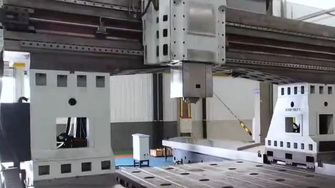
A moving-beam gantry machining center supports mass aluminum production through low moving inertia, fast acceleration, stable thermal behavior, high-speed spindle integration, and efficient chip evacuation. The fixed table also keeps dynamic performance consistent when workpiece weight changes.
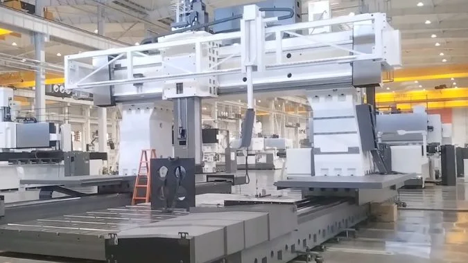
Aluminum machining looks simple because cutting forces are usually low1. Yet mass production adds harder demands. The machine must make frequent direction changes, hold accuracy for long shifts, and remove a large volume of chips. The following structural factors show why a moving-beam GMC can meet these demands.
Why Is the Moving Beam Structure More Suitable for Rapid Movement Compared to Table Movement?
A moving table must carry every kilogram of the workpiece. That changing load slows acceleration, increases reversal shock, and makes stable production settings harder to maintain.
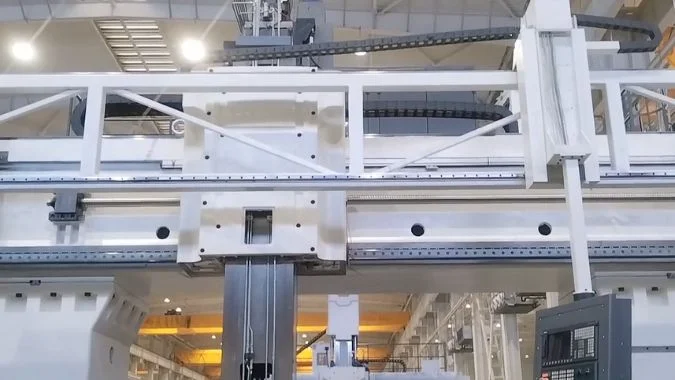
A moving-beam structure moves a lighter and more constant mass while the table and workpiece remain fixed. The stable inertia allows faster acceleration, more consistent rapid traverse, easier servo tuning, and lower mechanical shock during frequent starts, stops, and direction changes.
Constant Moving Mass Improves Motion Control
A moving-table machine must accelerate the table, fixture, and workpiece together. The total moving mass changes with every production job. A large aluminum plate can also place its center of gravity away from the drive line. This condition creates a larger inertial load and can produce an overturning moment during rapid direction changes.
A moving-beam GMC keeps the workpiece stationary. The drive system moves the beam and spindle assembly instead. This moving mass remains nearly constant from one batch to another. The controller can therefore use stable servo parameters without making large changes for different workpiece weights.
| Motion factor | Moving-beam GMC | Moving-table GMC |
|---|---|---|
| Moving load | Light and nearly constant | Heavy and dependent on the workpiece |
| Acceleration | High and repeatable | Limited by the maximum expected load |
| Rapid traverse | Consistent across different jobs | Often reduced for heavy parts |
| Reversal shock | Lower | Higher |
| Floor space | More compact for long workpieces | Extra space is needed for table travel |
Stable Acceleration Shortens Non-Cutting Time
Mass production includes many positioning moves. Tool changes, hole patterns, pockets, and separated features create repeated non-cutting travel. A small saving during each move becomes a large saving across hundreds of parts.
The moving beam follows the physical rule of keeping heavy objects still and moving lighter parts2. Lower inertial force reduces stress on guideways, screws, couplings, and servo motors. Dual-side synchronized drives can also control the beam without the backlash amplification caused by high-inertia reversal. These features support rapid traverse rates that remain stable even when a heavier workpiece enters production.
How Does Reduced Axis Inertia Benefit High-Feed Contouring in High-Speed Aluminum Machining?
Complex aluminum contours contain corners, arcs, and short toolpath segments. High inertia causes tracking delay, overshoot, surface ripples, and unwanted corner rounding at high feed rates3.
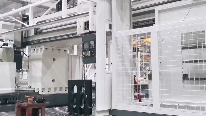
Reduced axis inertia allows the servo system to accelerate, brake, and reverse more quickly. This response improves contour tracking, supports higher control gains, reduces following error, and protects surface quality during high-feed machining of complex aluminum profiles.
Faster Response Protects Contour Accuracy
High-feed contouring does not depend only on spindle speed. Each linear axis must also follow thousands of small commands. The control system constantly changes axis speed as the cutter enters a corner, follows an arc, or moves across a curved surface. A heavy axis continues moving after the command starts to change. This motion creates lag4 and can push the cutter away from the programmed path.
A lower moving mass requires less motor torque for the same acceleration. The servo can respond faster and use higher position-loop and velocity-loop gains. Feedforward settings can also become more effective because the mechanical system reacts with less delay.
| Contouring condition | Effect of lower inertia |
|---|---|
| Sharp corner | Faster braking reduces corner overcut |
| Small arc | Better tracking limits radius error |
| Short line segment | Less time is lost during acceleration |
| Direction reversal | Lower shock reduces vibration |
| Curved surface | Smoother motion reduces visible ripples |
High Feed Becomes Useful Instead of Merely Possible
Aluminum alloys often allow feed rates of 20–40 m/min or more5 when tooling, spindle power, and machine configuration permit. Yet a high programmed feed has little value if the controller must slow down at every corner. Reduced inertia allows the axes to spend more time near the commanded feed.
Lower inertial forces also reduce changing loads on guideways and transmission parts. This reduction limits temporary elastic deformation during acceleration and braking. A rigid box-type beam, optimized rib placement, and a balanced dual-drive system can improve the stiffness-to-mass ratio further. Linear motors or low-inertia ball screws can add a more direct response. Correct servo tuning remains important because excessive gain can still create oscillation. The mechanical design and control settings must work as one system.
Why Is High-RPM Electric Spindle Integration More Effective on a Moving Beam Structure?
A high spindle speed alone cannot guarantee productive aluminum machining. A poorly supported spindle can introduce heat, vibration, long overhang, and delayed axis response.
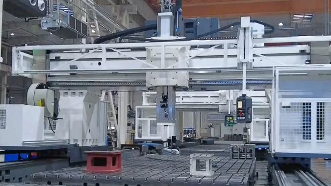
A moving-beam structure places the electric spindle within a light, rigid, and thermally balanced assembly. The short spindle overhang improves bending stiffness, while the centered heat source and low moving mass support rapid response, stable precision, and high-speed cutting.
Short Overhang Raises the Chatter Threshold
High-speed aluminum milling often uses a small axial depth of cut, a high feed rate, and a high spindle speed. This process needs a rigid spindle connection because even a small vibration can leave marks on a finished wall or floor6.
A moving-beam design can mount the spindle head directly on or within the beam. The resulting ram overhang can remain short. A shorter lever arm limits bending under cutting and acceleration loads7. The structure can therefore maintain a higher chatter threshold during high-speed milling.
| Integration point | Production benefit |
|---|---|
| Short spindle overhang | Higher bending stiffness |
| Centered spindle position | Balanced loading across the beam |
| Electric spindle drive | Fast response without a long transmission chain |
| Lightweight beam | Better acceleration and lower energy use |
| Symmetrical support | More predictable thermal movement |
Thermal Symmetry Supports Long Production Runs
An electric spindle generates heat through the motor, bearings, and cutting process. Uneven heat can move the tool center and create dimensional drift8. This problem becomes important when the machine runs for several shifts.
Many moving-beam machines use a symmetrical beam, twin columns, and dual-side drives. The spindle sits close to the structural center. This layout helps distribute heat more evenly across the supporting structure. Thermal growth can then occur mainly along a predictable axis rather than twisting the X-Y geometry. Spindle cooling, temperature sensors, and compensation software can improve this behavior.
The combination also reduces unnecessary transmission parts. A high-speed electric spindle provides direct rotational response, while the light beam provides fast linear response. Spindle speeds from 10,000 to 24,000 rpm can suit many aluminum applications9, depending on the tool diameter and required torque. The complete system can support high material removal without depending on spindle speed alone.
How Does Moving Beam GMC Solve Large-Volume Aluminum Chip Evacuation?
Aluminum machining creates long curls, light nests, and sticky wet chips. Weak conveyors and narrow channels can clog quickly, stop production, and contaminate cutting fluid.
A moving-beam GMC handles large chip volumes with a widened chain-plate conveyor, high-flow and high-pressure flushing, steep bed drainage, and solid-liquid separation. These systems move bulky non-magnetic chips away from the cutting area while recovering cleaner coolant.
The Conveyor Must Match Aluminum Chip Behavior
Aluminum chips are non-magnetic. A magnetic conveyor cannot collect them effectively10. A standard screw conveyor can also compress long curls into dense bundles. This compression can cause clogging, friction, and heat.
A chain-plate conveyor provides a wide carrying surface and high load capacity11. The plate design can transport long, curly, or block-shaped chips without relying on magnetism. A customized conveyor width should match the machine guideway width and full working travel. This coverage prevents chips from collecting outside the transport area.
| Chip-control component | Main function |
|---|---|
| Widened chain-plate conveyor | Carries large volumes of non-magnetic chips |
| High-flow coolant nozzles | Push chips toward the collection inlet |
| High-pressure flushing | Breaks nests and cleans covers |
| Vibrating screen | Separates large solids from coolant |
| Cyclone separator | Removes finer particles from the liquid |
| Chip-breaking scraper | Stops long chips from wrapping around the shaft |
Bed Geometry Must Guide Every Chip
The fixed table makes it easier to build wide drainage paths around the work zone. Bed surfaces should use slopes of about 30 degrees or more where the machine design allows. Wide channels should lead toward the chip collection ports. Smooth covers should also remove pockets where wet aluminum can settle.
High-flow nozzles near the tool move chips before they form a nest. Additional nozzles near the conveyor inlet prevent bridging. Pneumatic blowing can help when long profiles create scattered chips, but the air system must not spread chips into guideways or electrical areas.
A vibrating screen or cyclone separator should treat the coolant before recirculation. Early solid-liquid separation lowers the oil content of discharged chips and reduces sludge inside the coolant tank. Large U-groove aluminum cutters can also produce short, controlled curls and reduce built-up edge. Daily checks should cover chain tension, screen blockage, nozzle direction, and accumulated sludge. Aluminum-specific cutting fluid can further reduce staining, corrosion, and sticky chip deposits.
Conclusion
Moving-beam GMCs combine stable dynamics, accurate high-feed contouring, effective spindle integration, and controlled chip evacuation, making them a strong platform for repeatable aluminum mass production.
-
"The Influence of the Machining Parameters of AW-7020 … – PMC", https://pmc.ncbi.nlm.nih.gov/articles/PMC12072895/. Research comparing specific cutting forces across metals shows aluminum alloys typically require 30-60% lower cutting forces than steel under comparable machining conditions, though exact values depend on alloy composition and machining parameters. Evidence role: statistic; source type: research. Supports: that aluminum alloys generally require lower cutting forces than ferrous materials during machining operations. Scope note: Direct comparison is limited because cutting forces vary significantly with specific alloy grades, tool geometry, and cutting conditions ↩
-
"Newton’s Laws of Motion | Glenn Research Center – NASA", https://www1.grc.nasa.gov/beginners-guide-to-aeronautics/newtons-laws-of-motion/. Newton’s second law (F = ma) establishes that acceleration is inversely proportional to mass when force is constant, meaning systems moving lighter components can achieve higher acceleration with the same motor force. Evidence role: mechanism; source type: encyclopedia. Supports: that reducing moving mass improves acceleration for a given applied force. ↩
-
"Combined contour error control method for five-axis machine …", https://pmc.ncbi.nlm.nih.gov/articles/PMC12098878/. Research on high-speed contouring shows that increased axis inertia amplifies following error during acceleration and deceleration, resulting in corner rounding, trajectory overshoot, and periodic surface marks when feedrates exceed the system’s dynamic response capability. Evidence role: mechanism; source type: research. Supports: that high moving mass in CNC axes increases following error, overshoot, and contouring inaccuracy during high-speed direction changes. Scope note: The severity of these effects depends on controller tuning, feedforward compensation, and jerk limits, not solely on inertia ↩
-
"Modeling and Control of Contouring Errors for Five-Axis …", https://research.engr.oregonstate.edu/mpcl/resources/5-Ax-CC1.pdf. Motion control research demonstrates that following error in servo systems increases proportionally with load inertia, as higher-inertia axes require longer settling times and exhibit greater phase lag during direction changes. Evidence role: mechanism; source type: research. Supports: that higher moving mass increases following error and response delay in servo-controlled axes. Scope note: The relationship can be partially compensated through feedforward control and higher loop gains, though physical inertia limits remain ↩
-
"Speeds and Feeds", https://web.mae.ufl.edu/designlab/Advanced%20Manufacturing/Speeds%20and%20Feeds/Speeds%20and%20Feeds.htm. High-speed machining literature reports feed rates for aluminum alloys ranging from 15-50 m/min in production environments, with specific values depending on workpiece geometry, tool diameter, and desired surface finish. Evidence role: statistic; source type: research. Supports: that modern aluminum machining operations commonly employ feed rates in the range of 20-40 m/min or higher. Scope note: Achievable feed rates vary significantly based on machine rigidity, tooling quality, and specific alloy grade ↩
-
"Studying the Factors Affecting Tool Vibration and Surface …", https://pmc.ncbi.nlm.nih.gov/articles/PMC10223796/. Studies on machining dynamics demonstrate that tool vibration transfers periodic displacement patterns onto the machined surface, creating visible chatter marks, increased surface roughness, and dimensional variation. Evidence role: mechanism; source type: research. Supports: that vibration and chatter during machining operations produce visible surface irregularities and increased roughness. ↩
-
"Overhanging Beam Calculator — Single Overhang", https://www.firgelliauto.com/blogs/engineering-calculators/overhanging-beam-calculator-single-overhang?srsltid=AfmBOopr92hrP2U6dNXB0UA_BavbEIY1hMA56471dNcDjecNXhVPK6dK. Beam mechanics principles establish that cantilever deflection increases with the cube of overhang length, meaning shorter spindle extensions provide substantially higher stiffness and lower tool point displacement under identical cutting forces. Evidence role: mechanism; source type: education. Supports: that reducing cantilever length increases bending stiffness and reduces deflection under load. ↩
-
"Robust Machine Tool Thermal Error Modeling Through …", http://wumrc.engin.umich.edu/wp-content/uploads/sites/51/2013/08/08JMSEZhuMachinetoolthermalerrorcompensation.pdf. Machine tool thermal behavior research identifies uneven heat distribution as a major source of positioning error, with thermal growth causing tool displacement through structural expansion, spindle growth, and geometric distortion that varies with operating time and load distribution. Evidence role: mechanism; source type: research. Supports: that asymmetric thermal expansion in machine structures causes tool center point displacement and dimensional errors. Scope note: Thermal error magnitude depends on machine design, materials, cooling systems, and ambient conditions; some designs are inherently more thermally stable ↩
-
"Speeds and Feeds", https://web.mae.ufl.edu/designlab/Advanced%20Manufacturing/Speeds%20and%20Feeds/Speeds%20and%20Feeds.htm. Machining handbooks and cutting tool manufacturer data indicate that aluminum milling operations typically employ spindle speeds between 8,000-30,000 rpm, with specific values determined by tool diameter, surface speed requirements, and alloy hardness. Evidence role: general_support; source type: research. Supports: that spindle speeds in the 10,000-24,000 rpm range are commonly used for aluminum machining. Scope note: Optimal spindle speed depends on cutter diameter; smaller tools require higher RPM to achieve recommended surface speeds ↩
-
"electromagnetism – Is aluminium magnetic?", https://physics.stackexchange.com/questions/10827/is-aluminium-magnetic. Aluminum is classified as a paramagnetic material with extremely weak magnetic susceptibility, making magnetic separation ineffective for aluminum chip removal, unlike ferrous materials that respond strongly to magnetic fields. Evidence role: definition; source type: encyclopedia. Supports: that aluminum is non-ferromagnetic and therefore not attracted to magnetic chip conveyors. ↩
-
"CNC Chip Conveyors", https://hennigworldwide.com/chip-conveyors. Industrial material handling literature describes chain-type conveyors as suitable for long, stringy, or non-magnetic chips because their open plate design prevents compression and jamming that commonly occurs with screw conveyors. Evidence role: general_support; source type: other. Supports: that chain-type conveyors can transport bulky, tangled, or curled chips more effectively than screw or magnetic alternatives. Scope note: Performance depends on proper chain tension, plate width, and regular maintenance; not all designs handle fine chips equally well ↩

Chris Lu
Leveraging over a decade of hands-on experience in the machine tool industry, particularly with CNC machines, I'm here to help. Whether you have questions sparked by this post, need guidance on selecting the right equipment (CNC or conventional), are exploring custom machine solutions, or are ready to discuss a purchase, don't hesitate to CONTACT Me. Let's find the perfect machine tool for your needs.