

What Causes Chips to Accumulate Around the Chuck?
Chips around the chuck can scratch parts and interrupt production. Effective control starts with finding why chips stay long, travel toward the jaws, or fail to clear.
Chips accumulate around the chuck because poor chip breaking and poor evacuation allow them to remain near rotating parts. Long chips catch on the workpiece or jaws and collect more material. Low feed, shallow cuts, unsuitable insert geometry, and misdirected coolant can contribute.
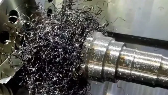
The shape of a chip often explains how it reached the chuck. A long ribbon can catch a jaw and pull more material into a tangled mass. Short chips can also collect in recesses without forming a wrap. A useful inspection begins with the chips produced by the operation that creates the buildup.
What Can Chip Shape Tell You About a Turning Operation?
Chip changes can reveal trouble before a part fails inspection. Reading their shape alongside tool condition helps identify cutting problems before they cause more damage.
Chip shape shows how the material deforms, curls, and breaks during turning. Long ribbons suggest weak chip control, and consistent short curls often indicate effective breaking. A sudden change can signal tool wear or altered cutting conditions. Material type must guide the interpretation.
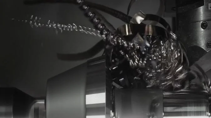
Different materials produce different chip patterns
Ductile materials, including aluminum, copper, and low-carbon steel, can form continuous ribbons.1 These chips may come from a smooth cut, but their length makes them difficult to clear.
Brittle materials, including many cast irons, often produce separate fragments.2 Fragmented chips alone do not prove that the tool is worn or that the feed is incorrect.
| Chip appearance | What it may indicate | Useful follow-up check |
|---|---|---|
| Long ribbon or continuous helix | The chip is curling without breaking | Compare feed and depth with the insert’s working range |
| Short, separate curls | The chip breaker is producing manageable pieces | Check that the pieces leave the cutting zone |
| Serrated or segmented chip | Deformation varies along the chip | Compare with the material and check for vibration |
| Small fragments | The material may naturally form discontinuous chips | Inspect surface finish and cutting-edge condition |
| A sudden change during the same job | The tool or cutting conditions may have changed | Inspect wear, buildup, and coolant delivery |
Chip appearance needs supporting evidence
A chip sample is most useful when its material, operation, and cutting settings are known. Comparing chips from the same cut makes changes easier to interpret.
Color provides another clue, but it should not become a fixed pass-or-fail rule. A color change alone does not establish tool wear or excessive temperature. The operator should also examine the cutting edge, surface finish, and coolant supply.
Long chips do not automatically mean that feed is too high. The selected chip breaker may be receiving a chip that is too thin to break effectively.
How Do Feed and Depth of Cut Affect Chip Breaking?
Light cuts can produce long chips that crowd the chuck. Matching feed and depth to the chip breaker gives parameter changes a clear purpose.
Feed strongly affects chip thickness, and depth of cut affects chip width and engagement with the insert geometry. Increasing an excessively low feed can improve chip breaking. Both settings must remain within the chip breaker’s recommended range and the limits for surface finish, cutting load, and stability.
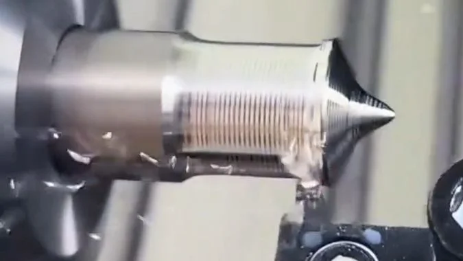
Feed must suit the chip breaker
A chip breaker uses its groove shape to curl the chip and encourage it to break.3 A feed below its intended range can produce a thin ribbon that does not bend enough to separate.4
A controlled feed increase is a useful trial in this situation. The thicker chip can engage the groove more effectively. The operator must also check cutting load and surface finish because a higher feed is not suitable for every part.
An excessive feed creates another problem. The chip can load the cutting edge heavily, and aggressive breaking can shorten insert life. The aim is a manageable chip within a stable cutting process.
Depth of cut changes how the geometry works
A shallow cut may engage mainly the insert nose. A large nose radius and a chip breaker intended for roughing may perform poorly with a small finishing allowance.
A greater depth can improve engagement in a suitable setup, but it also changes chip width and cutting load. Depth should be reviewed together with feed and insert geometry.
| Cutting condition | Likely limitation | Suitable adjustment to evaluate |
|---|---|---|
| Thin, continuous chips at low feed | Feed is below the groove’s effective range | Increase feed within the recommended limits |
| Long chips during shallow finishing | The geometry does not suit the allowance | Select a finishing chip breaker or suitable nose radius |
| Heavy chips and rising cutting load | The cut exceeds the useful operating range | Reduce load or choose a more suitable geometry |
| Good chip control during roughing only | Roughing and finishing need different conditions | Review each operation separately |
The insert supplier’s feed-and-depth chart provides a better starting point than one universal setting. A finishing pass cannot simply become deeper if that removes material needed for the final dimensions.
Cutting speed can then be reviewed for the material and tool. A speed change should support chip control without creating adhesion, rapid wear, or an unacceptable surface.
Why Do Long Chips Wrap Around the Tool or Workpiece?
An unbroken chip can become a growing nest around rotating parts. Identifying its first contact point helps stop repeated wrapping and surface damage.
Long chips wrap because they remain connected after leaving the cutting edge and contact the rotating workpiece or chuck. Rotation can pull them around nearby parts. Ductile material, weak chip breaking, unsuitable chip flow, and obstructions near the jaws increase the chance of entanglement.
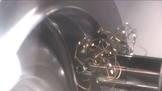
Continuous cutting creates a continuous escape problem
During an uninterrupted turning cut, material keeps flowing across the insert. The chip needs to break or move clear of the workpiece.
Aluminum, copper, and soft steels can produce flexible ribbons or long coils. A coil may look compact as it leaves the insert, but it can still be one continuous piece. Its length allows it to bridge the distance between the tool and the chuck.
The first contact matters. A ribbon that touches a rotating surface can wind around it and capture more chips. The resulting nest can scratch the finished surface, strike the tool, or obstruct coolant delivery.
The collection point helps identify the cause
Jaw steps, recesses, and exposed features can retain chips. A shoulder near the cutting zone can also redirect the chip toward the tool or chuck.
| Where chips collect | Likely issue to investigate | Process response |
|---|---|---|
| Around the tool holder | Long chips curl back toward the tool | Review chip breaker selection and flow direction |
| Around the workpiece | Chips remain long enough to contact the rotating surface | Improve breaking and guide chips clear |
| Between the jaws | Chips reach gaps that retain them | Review the evacuation path and approved flushing arrangement |
| Around a nearby shoulder | The feature obstructs the chip’s path | Review insert geometry and the cutting sequence |
Chip shape and chip direction both matter. Shorter chips reduce wrapping, but the machine still needs a clear route for them to leave the chuck area.
Manual clearing requires a stopped machine and the approved chip-removal procedure. The operator should never pull a chip from rotating work. Any proposed changes to the chuck or jaws need review by the workholding supplier.
How Can Coolant Direction Help Clear the Cutting Zone?
Coolant can wet the workpiece and still miss the chip source. Correct targeting helps prevent fresh chips from returning to the tool or collecting near the jaws.
Coolant helps clear the cutting zone when its jet reaches the active cutting edge and supports chip flow away from the tool, finished surface, and chuck. Precise delivery can also assist chip breaking. Nozzle position, available flow, and an open evacuation route must work together.
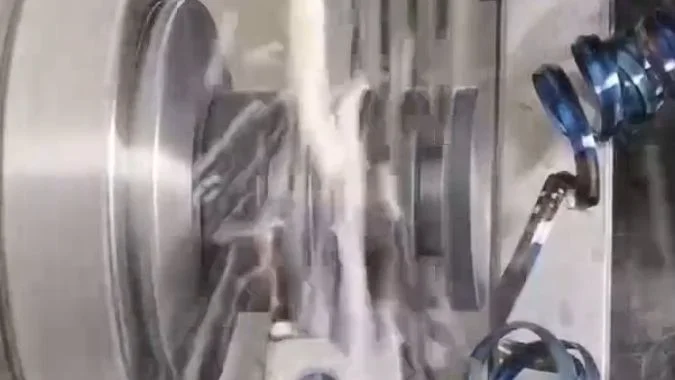
The jet needs a clear target
The useful target is the cutting zone where the chip leaves the insert. A jet that strikes the holder or an existing chip nest may not reach that area.
Coolant directed toward the tool-chip contact region can assist chip curling and removal.5 It also provides cooling and lubrication. A separate flushing stream may help carry loose chips toward the machine’s collection route.
A fixed spray angle is not suitable for every turning setup. The useful direction depends on the insert, holder, workpiece shape, and cutting position. The nozzle should follow the tool supplier’s guidance and the observed chip path.
| Coolant observation | What may be happening | Point to check |
|---|---|---|
| The holder is wet but chips remain at the edge | The jet misses the active cutting zone | Nozzle alignment and obstructions |
| Chips move toward the jaws | The flow carries chips into a collection point | Discharge direction and the escape route |
| Chip control worsens as a nest grows | Accumulated chips block delivery | Chip breaking and access to the cutting edge |
| Delivery weakens during the cycle | Flow is restricted or inconsistent | Nozzles, filters, and coolant supply |
Precision and flow serve different purposes
A precisely directed jet can help control the chip close to its source. Adequate flow then helps remove the separated pieces. Pressure alone cannot compensate for poor alignment or a blocked evacuation path.
A compatible high-pressure coolant system may improve control of difficult chips, but its pump, holders, nozzles, and connections must suit that pressure.6 A standard flood nozzle should not simply be treated as a high-pressure nozzle.
Nozzle adjustments should be made with the machine stopped. The next trial should confirm that chips leave the cutting zone and reach the collection area instead of moving from one trapped location to another.
Conclusion
Chuck-area chip buildup decreases when the insert, feed, cutting depth, and coolant direction work together. Effective chip breaking and a clear evacuation path are both necessary.
-
"Chip formation", https://en.wikipedia.org/wiki/Chip_formation. Machining literature documents that materials with high ductility, including aluminum alloys, copper, and low-carbon steels, typically produce continuous or ribbon-type chips due to their capacity for extensive plastic deformation without fracture. Evidence role: general_support; source type: research. Supports: the tendency of ductile materials to form continuous chip types during machining. ↩
-
"Research Article A chip formation mechanism taking into …", https://www.sciencedirect.com/science/article/abs/pii/S0890695524000361. Research on chip formation mechanisms shows that brittle materials such as cast irons produce discontinuous or fragmented chips because their limited ductility causes fracture during shear deformation rather than continuous plastic flow. Evidence role: mechanism; source type: research. Supports: the mechanism by which brittle materials produce discontinuous or fragmented chips. ↩
-
"On the Mechanism of Chip Breaking | J. Manuf. Sci. Eng.", https://asmedigitalcollection.asme.org/manufacturingscience/article/101/3/241/426775/On-the-Mechanism-of-Chip-Breaking. Research on cutting tool design demonstrates that chip breaker grooves impose geometric constraints that force the flowing chip to curl with a specific radius, creating bending stresses that promote fracture when the chip’s curvature exceeds the material’s bending capacity. Evidence role: mechanism; source type: research. Supports: the mechanism by which chip breaker groove geometry induces chip curling and fracture. ↩
-
"Impact of Chip Breaker Geometry on the Performance … – PMC", https://pmc.ncbi.nlm.nih.gov/articles/PMC11902139/. Studies of chip breaker performance show that chips thinner than the breaker’s design range lack sufficient stiffness to generate the bending stresses required for fracture, resulting in continuous chip formation despite the presence of chip control geometry. Evidence role: mechanism; source type: research. Supports: the relationship between chip thickness (determined by feed rate) and chip breaker effectiveness. ↩
-
"Inline solutions for catching super fine chips in coolant lines", https://www.facebook.com/groups/769782850345135/posts/1379828012673946/. Studies of cutting fluid delivery show that coolant directed at the tool-chip interface can influence chip curl radius through thermal effects and mechanical forces, while also providing momentum to assist chip evacuation from the cutting zone. Evidence role: mechanism; source type: research. Supports: the influence of directed coolant on chip curling behavior and removal. Scope note: The effect varies significantly with coolant pressure, flow rate, and nozzle design ↩
-
"Purdue develops ‘intrachip’ micro-cooling system for high- …", https://www.purdue.edu/newsroom/archive/releases/2017/Q4/purdue-develops-intrachip-micro-cooling-system-for-high-performance-radar,-supercomputers—.html. Research on advanced coolant delivery systems indicates that high-pressure coolant (typically 70-200 bar) can improve chip breaking and evacuation for difficult-to-machine materials, though implementation requires toolholders, seals, and delivery systems specifically designed for elevated pressures. Evidence role: general_support; source type: research. Supports: the effectiveness of high-pressure coolant systems in chip control and the system requirements for safe operation. ↩

Chris Lu
Leveraging over a decade of hands-on experience in the machine tool industry, particularly with CNC machines, I'm here to help. Whether you have questions sparked by this post, need guidance on selecting the right equipment (CNC or conventional), are exploring custom machine solutions, or are ready to discuss a purchase, don't hesitate to CONTACT Me. Let's find the perfect machine tool for your needs.