

How to Choose Molybdenum Wire Diameter for Your HS-WEDM or MS-WEDM?
A thick molybdenum wire cuts faster and leaves a wide kerf. A thin wire holds a sharper corner and breaks more easily. Diameter must follow thickness and accuracy.
Molybdenum wire diameter for an HS-WEDM or MS-WEDM is chosen from part thickness and the accuracy needed. Common sizes are 0.12–0.20 mm. A first cut often uses 0.18 mm. A skim cut uses 0.15 mm or thinner. Above 0.23 mm on a fast-wire machine causes pile-up.
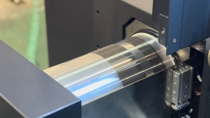
A 0.18 mm wire and a 0.12 mm wire do not cut the same slot. The thicker wire opens a wider kerf and runs faster. The thinner wire leaves a smaller radius in an inside corner. Part thickness and the corner on the drawing decide which diameter belongs on the machine.
What Does Wire Diameter Do in Kerf Width, Inside Corner, and Cutting Speed?
One diameter cannot serve kerf, corner, and speed at once. A wide slot, a blunt corner, or a slow cut is the result. The three effects must be read together.
Wire diameter sets kerf width, the radius left in an inside corner, and cutting speed. Thicker wire widens the kerf and cuts faster, but leaves a larger corner arc. Thinner wire narrows the kerf and can approach a sharper corner.
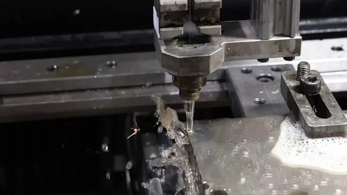
Kerf width
Kerf width is about the molybdenum wire diameter plus the discharge gap on both sides1. A thicker wire opens a wider slot. A thinner wire opens a narrower slot. Program compensation is the wire radius plus the gap on one side. The wire also wears thinner during the job, so the kerf and the finished size drift. Diameter should be measured on a set schedule, and the compensation value should be entered again.
Inside corner
A thicker wire leaves a larger arc in an inside corner. A sharp corner is then hard to reach. A thinner wire leaves a smaller round, so the path can come closer to a sharp corner. Small molds with sharp corners and narrow slots need that thinner wire. Wire EDM for stamping molds is a separate process choice. Diameter still sets how small the leftover corner can be.
Cutting speed
A thicker wire can carry more discharge current, so the cut is faster. Thick parts favor that speed. The same thick wire also lowers surface quality. Part thickness, material, and the accuracy on the drawing must be read together before the diameter is locked.
Common diameters on HS-WEDM and MS-WEDM
Conventional fast-wire and medium-wire work uses 0.12–0.20 mm. A first cut often uses 0.18 mm. A fine finish pass switches to 0.15 mm or thinner. A target of Ra 0.4 μm or better favors 0.12–0.15 mm, with tension held steady. Thick parts and high current favor 0.18 mm or above. HS-WEDM and MS-WEDM differ as machines. The diameter rule on either machine still follows the part.
| Effect | Thicker wire | Thinner wire |
|---|---|---|
| Kerf | Wider. Diameter plus both-side gap | Narrower |
| Inside corner | Larger leftover arc | Smaller radius, closer to a sharp corner |
| Cutting speed | Faster. Better on thick parts | Slower |
| Surface | Usually worse | Better when tension is held |
| Typical size | First cut at 0.18 mm, or thicker for heavy stock | Skim at 0.15 mm, or 0.12–0.15 mm for fine finish |
Why Does a Thicker Molybdenum Wire Carry Current Better on a Thick Steel Block?
A thick steel block needs more average current. A thin wire overheats and snaps under that load. Cross-section is what sets the current the wire can carry.
A thicker molybdenum wire carries current better on a thick steel block because its cross-section is larger. At about 150 A/mm², 0.18 mm wire can take about 3.82 A. A 0.12 mm wire is near 1.74 A.
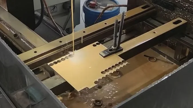
Why section sets the current
Wire EDM melts metal with pulse discharge. The molybdenum wire is the electrode that carries that current. Current capacity follows cross-section. A thicker wire can carry more current before it fails. An industry reference puts the cutting limit near 150 A/mm². At that density, tensile strength falls to about one-third or one-quarter of the original strength2. On that basis, 0.12 mm wire is near 1.74 A. 0.18 mm wire is near 3.82 A. The gap between those two limits is large.
What a thick steel block demands
A thick block has a long discharge path. Chips are hard to clear. Effective erosion needs a higher average current. The block also turns more of that energy into heat. Thick wire takes the current. It has lower resistance and makes less heat in the wire itself. A local hot spot is then less likely to pull the wire apart. In thick steel, 0.18 mm wire is much more stable than 0.12 mm wire.
Where thicker stops helping
The wider kerf and a slightly worse profile are the cost of that current. Thicker is not always better. Above 0.23 mm on a fast-wire machine, the wire can pile up and deflect. That size does more harm than good. Thick stock and high current take 0.18 mm or thicker. Small precise parts that need finish take 0.12–0.15 mm.
| Wire | Approx. current near 150 A/mm² | Fit on a thick steel block |
|---|---|---|
| 0.12 mm | About 1.74 A | Overheats and breaks under the current a thick block needs |
| 0.18 mm | About 3.82 A | More stable. Lower resistance and less heat in the wire |
| Above 0.23 mm on fast-wire | Higher section, but poor wire behavior | Pile-up and deflection. Not a gain |
| 0.12–0.15 mm on small precise parts | Lower current | Finish and corner, not thick-block speed |
What Happens to Finish if One Diameter Is Forced Through Both Rough and Skim Cuts?
One wire that roughs and then skims copies the roughing damage onto the face. Roughness stays high, and streaks appear. The wire must be checked or changed.
Forcing one molybdenum wire through both rough and skim cuts leaves a worn, pitted wire on the finish pass. Ra often stays at 1.2–1.4 μm and will not settle below 1.0 μm. Wear over 0.01 mm means the wire should be replaced.
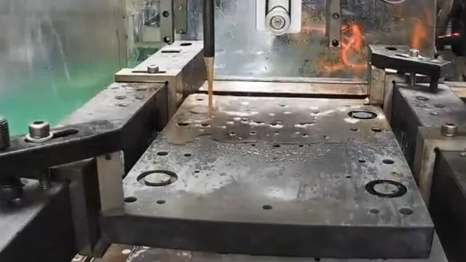
What the face shows
The same wire for roughing and skimming copies wire damage onto the part. Roughness will not settle below Ra 1.0 μm. It often sits at Ra 1.2–1.4 μm, or worse. Uneven wear or local pits leave regular light and dark streaks, like wire-jump marks. A thinning wire makes the discharge gap unstable. A short pulse interval then leaves irregular pits. Dirty fluid adds a yellow cast or carbon on the face.
Why the roughing wire cannot skim
High current in the rough cut thins the wire and puts micro-pits in its surface. Neither the new diameter nor that surface is stable enough for a skim. Wear over 0.01 mm is the usual change point. Past that loss, finish quality cannot be held. Roughing and skimming also want different tension. One wire moving between those states changes kerf width and surface texture. Deep discharge pits and the altered layer from the first cut may also be too deep for later passes to clear. The finish then has a ceiling.
What to change before the skim
Separate wires when the machine allows it. About 0.18 mm for roughing. 0.12–0.15 mm for skimming. Current capacity and kerf width then match each pass. If one wire must stay, measure it after roughing. Replace it when wear exceeds 0.01 mm. For the skim, hold pulse width within 4 μs3, slow the wire speed, and set tension at 12–14 N4. A finish below Ra 0.8 μm is basically out of reach on that same molybdenum wire5. Separate wires, or a slow-wire process, are the remaining paths.
| Check | Same wire through rough and skim | Separate wires |
|---|---|---|
| Wire after roughing | Thinned and micro-pitted | Roughing wire stops at the rough cut |
| Typical Ra | Often 1.2–1.4 μm. Hard to hold below 1.0 μm | Skim wire is 0.12–0.15 mm and still round |
| Wear limit | Over 0.01 mm: change before the skim | Not shared, so roughing wear does not enter the skim |
| Below Ra 0.8 μm | Basically not reachable | Separate wires, or slow-wire EDM |
| Skim settings if the wire must stay | Pulse width within 4 μs, slower wire, tension 12–14 N | Not required for a fresh skim wire |
Why Can a Thin Wire Break More Often on Interrupted Cuts and Poor Flushing?
Interrupted cuts and weak flushing pile heat and debris on a thin wire. The wire then burns or snaps. Flush pressure and the broken end show the cause.
A thin molybdenum wire breaks more often on interrupted cuts with poor flushing because heat and debris stay in a narrow kerf. The wire has less section, higher resistance, and less cooling. Breakage rises sharply when pump pressure is below 0.5 bar.
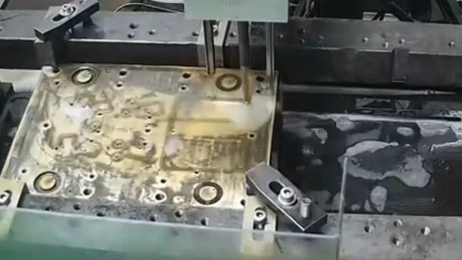
Interrupted cutting
An interrupted path makes the discharge jump between short circuit and open circuit. The wire takes repeated current shocks. An unstable discharge can also park an arc on one short length of wire. That spot overheats and breaks.
Poor flushing
Low flow, or a blocked path, keeps working fluid out of the kerf. Eroded debris stays in the slot. Short circuits form. Heat is not carried off. Wire temperature rises until the wire passes its limit. Breakage rises sharply when circulation pump pressure is below 0.5 bar. Fluid concentration should stay inside the maker’s recommended range.
Why thin wire fails first
A thinner wire has less cross-section. Resistance is higher. Current capacity is lower. Cooling is worse. The kerf is also narrower, so chips leave more slowly. The same heat and the same debris break a thin wire sooner than a thick wire.
What the broken end shows
A molten ball on the broken end points to overheating. Discharge settings and fluid supply are the first check. A flat end with no sign of melting points to a mechanical pull. Tension, guide pulleys, and electrical contact blocks are the first check.
| Condition | What it does to a thin wire | First check |
|---|---|---|
| Interrupted cut | Repeated shorts, opens, and a parked arc | Discharge stability on the break length |
| Flush below 0.5 bar | Heat and debris stay in the kerf | Pump pressure and flow into the slot |
| Fluid off the maker’s range | Poor cooling and poor chip removal | Concentration |
| Molten ball on the broken end | High-temperature break | Discharge parameters and fluid supply |
| Flat broken end, no melt | Mechanical pull | Tension, guide pulleys, contact blocks |
Conclusion
Thick steel takes 0.18 mm or thicker. Corners and skim cuts take 0.12–0.15 mm. A worn roughing wire should not stay on for the finish.
-
"Prediction of Kerf Width and Surface Roughness of Al6351 …", https://pmc.ncbi.nlm.nih.gov/articles/PMC8839751/. In wire electrical discharge machining, the kerf width is determined by the wire diameter plus the spark gap that forms on each side of the wire during the discharge process, with the gap typically ranging from 0.01 to 0.05 mm depending on machining parameters. Evidence role: mechanism; source type: encyclopedia. Supports: the geometric relationship between wire diameter, spark gap, and resulting kerf width in EDM. ↩
-
"Study of the Structure and Mechanical Properties after … – PMC", https://pmc.ncbi.nlm.nih.gov/articles/PMC8878319/. Research on molybdenum wire behavior under thermal and electrical loading demonstrates that elevated temperatures from current flow can reduce tensile strength substantially, with reductions of 50–75% observed at temperatures approaching the wire’s operational limits in EDM. Evidence role: mechanism; source type: paper. Supports: the effect of thermal loading on molybdenum wire mechanical properties. Scope note: The degree of strength reduction depends on temperature distribution, exposure time, and wire microstructure, making the relationship context-dependent rather than a fixed ratio. ↩
-
"Optimization of WEDM Parameters While Machining … – PMC", https://pmc.ncbi.nlm.nih.gov/articles/PMC9821652/. Research on wire EDM finishing parameters indicates that shorter pulse durations, typically in the range of 1–5 μs, produce finer surface finishes by reducing the energy per discharge and the resulting crater size on the workpiece surface. Evidence role: general_support; source type: paper. Supports: the relationship between pulse duration and surface finish in wire EDM. Scope note: Optimal pulse width depends on material properties, wire diameter, and desired finish, so the cited value represents a typical range rather than a universal setting. ↩
-
"Optimization of WEDM Parameters While Machining … – PMC", https://pmc.ncbi.nlm.nih.gov/articles/PMC9821652/. Studies on wire EDM process parameters indicate that wire tension for finishing operations typically ranges from 10–20 N depending on wire diameter and material, with higher tension improving dimensional accuracy but requiring careful control to avoid wire breakage. Evidence role: general_support; source type: research. Supports: typical wire tension ranges used in wire EDM finishing operations. Scope note: Optimal tension varies with wire diameter, material, and machine design, so the cited range represents common practice for typical wire sizes rather than a universal specification. ↩
-
"Experimental Investigation of Surface Roughness and … – PMC", https://pmc.ncbi.nlm.nih.gov/articles/PMC9920754/. Experimental investigations of wire EDM finishing demonstrate that achieving surface roughness below Ra 0.8 μm typically requires fresh wire and optimized finishing parameters, as wire degradation from prior cutting operations introduces surface irregularities that limit finish quality. Evidence role: general_support; source type: paper. Supports: surface finish limitations when using worn wire in wire EDM. Scope note: The achievable finish depends on multiple factors including material, wire type, and machine capability, so the cited threshold represents typical practice rather than a fundamental limit. ↩

Chris Lu
Leveraging over a decade of hands-on experience in the machine tool industry, particularly with CNC machines, I'm here to help. Whether you have questions sparked by this post, need guidance on selecting the right equipment (CNC or conventional), are exploring custom machine solutions, or are ready to discuss a purchase, don't hesitate to CONTACT Me. Let's find the perfect machine tool for your needs.