

Why Is a B-Axis Swiss Lathe Essential for Manufacturing Complex Medical Bone Screws and Implants?
Small medical implants leave almost no room for machining error. Multiple setups can create dimensional variation, surface damage, burrs, contamination, and costly production delays.
A B-axis Swiss lathe completes angled holes, drive slots, threads, curved surfaces, and multiple faces in one clamping. It supports slender parts near the cutting point, reduces setup errors, and can maintain batch tolerances near ±0.003 mm under validated machining conditions.
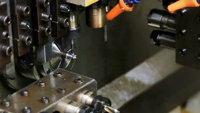
Medical bone screws can be shorter than 10 mm and include features near the 1 mm scale1. Their small size does not make them simple. Torx recesses, locking holes, variable threads, and thin sections create demanding machining conditions2. A B-axis adds the angular control needed to combine these operations on one platform. This process integration has a direct effect on accuracy, cycle time, surface quality, and part handling.
What Is the Function of the B-Axis on a Swiss-Type Lathe?
Standard turning cannot easily reach angled or curved features. Without angular control, each extra setup increases error, handling, and the risk of damaging a finished implant surface.
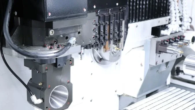
The B-axis rotates a tool head or machining unit around an angular centerline. It works with the X, Y, and Z axes to position cutting tools at selected angles for milling, drilling, tapping, slotting, chamfering, and contour machining.
How Does the B-Axis Expand Machining Capability?
The B-axis changes a Swiss-type lathe from a mainly turning-based platform into a flexible turn-mill machining center. Its exact rotation range depends on the machine design. Some systems provide a range such as 0–95°, while other configurations may offer about ±110°3. Servo control allows the axis to index to a set angle or move with other controlled axes.
This movement makes non-axial features accessible without removing the workpiece. A medical screw can receive an angled cross hole, a Torx recess, a chamfer, and a milled flat during one cycle. A dental abutment can receive an irregular surface, a hexagonal locking feature, and a multi-angle guide hole in the same setup.
The sliding guide bush also supports the bar close to the cutting point. This structure is useful when machining titanium or biodegradable material in diameters of about 0.5–2 mm4. It reduces bending and vibration while the B-axis controls tool orientation5.
| B-axis capability | Medical machining use | Main production benefit |
|---|---|---|
| Angular indexing | Angled holes and locking features | Fewer setups |
| Multi-axis movement | Curved surfaces and helical slots | Smoother feature transitions |
| Tool-angle control | Chamfers and edge finishing | Lower manual deburring demand |
| Turn-mill integration | Threads, flats, and drive recesses | One-clamping completion |
| Optimized cutting direction | Thin walls and micro-features | Fewer burrs and less deformation |
Why Is One-Clamping Completion Important for Implants?
Every new clamping operation introduces another datum transfer6. Even a small positioning difference can affect the relationship between a screw thread, drive recess, and locking hole. A B-axis keeps these features tied to the same machining reference.
Repeated handling can also mark a finished surface. It can leave clamp impressions or introduce particles before cleaning and passivation. One-clamping production does not remove the need for a validated cleaning process. It does reduce unnecessary contact and process movement. This reduction is valuable for parts with strict surface integrity and traceability requirements.
The cutting angle can also be adjusted for titanium alloys, cobalt-chromium alloys, stainless steel, and newer biodegradable materials7. A better tool approach can reduce burr formation and residual stress around thin walls. These conditions can support better fatigue performance when the complete manufacturing process is properly controlled.
Can the B-Axis Perform Operations on Both the Main Spindle and the Sub-Spindle?
Poor spindle coordination can leave one side of a machine waiting. It can also create confusion about whether one B-axis can machine two separate workpieces at once.
A B-axis may be configured to serve the main spindle, the sub-spindle, or both machining zones at different times. However, one physical B-axis normally cannot cut separate parts at both spindles simultaneously. Machine layout and tool-bank access determine its actual reach.
How Do the Main and Sub-Spindles Work Together?
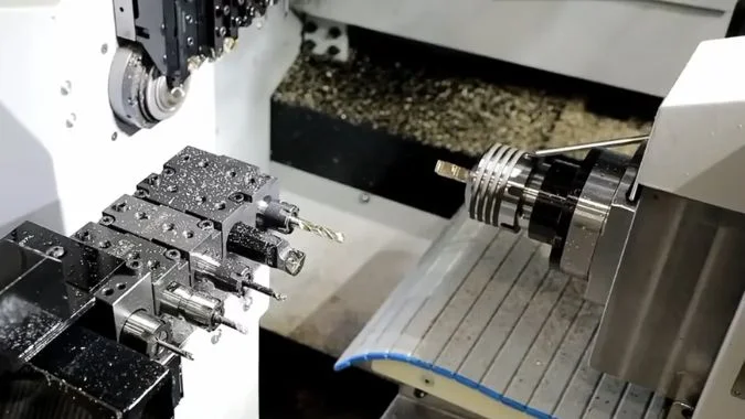
A dual-spindle Swiss-type lathe often uses independent CNC channels. The main spindle performs front-side operations while the sub-spindle receives the part and completes back-side work. After transfer, the main spindle can begin machining the next section of bar while the sub-spindle finishes the previous part. This parallel structure can reduce idle time.
The B-axis is normally mounted on a defined tool bank, gang slide, or independent tool unit. Its physical location controls which spindle it can reach. Some machine designs allow the B-axis tooling to approach both spindle positions. Other designs dedicate it mainly to the main spindle or the sub-spindle. A machine specification must therefore be checked before a process plan is approved.
A single B-axis still occupies only one physical machining position at a time. It may mill an angled feature at the main spindle and later machine a back-side feature at the sub-spindle. It cannot normally perform both cuts at the same instant.
| Machine activity | Main spindle | Sub-spindle | B-axis role |
|---|---|---|---|
| Front-side turning | Active | Available or working | May index tools for angled features |
| Part transfer | Synchronizing | Synchronizing | Usually clear of the transfer area |
| Back-side finishing | Starts the next part | Finishes the previous part | May serve the accessible spindle zone |
| Parallel production | Machines new bar stock | Completes transferred component | Handles one reachable operation at a time |
What Medical Parts Benefit From Dual-Spindle Production?
Orthopedic screws often require complete machining on both ends. The main spindle can turn the thread profile, form the head, and mill the drive recess. The sub-spindle can grip the component before cutoff and complete the back end. It can also drill, face, chamfer, or finish a tip feature.
This process avoids dropping a nearly finished micro-part into a tray for later reloading. That point matters because very small screws are difficult to orient and clamp again. Secondary loading also creates opportunities for scratches, mixed batches, and datum errors.
Cycle-time gains depend on operation balance. If back-side machining takes much longer than front-side work, the sub-spindle can become the limiting station. Process planning should distribute operations where possible. Simultaneous tool use, toolpath changes, and suitable cutting data can improve this balance. Under the right conditions, integrated machining can reduce cycle time by more than 30%, while some parts may achieve a three-to-five-times gain8 over fragmented multi-machine production.
How Does the B-Axis Eliminate the Need for Costly Angled Live Tool Attachments?
Dedicated angled live tools increase cost, occupy tool positions, and may not provide the spindle speed needed for micro-features. They also add maintenance and setup demands.
The B-axis reduces dependence on angled live tool attachments by rotating a standard tool or external high-frequency spindle to the required cutting angle. It does not remove every live-tool requirement, but it can replace many fixed-angle operations with a simpler and less costly setup.
What Is the Practical Substitution Method?
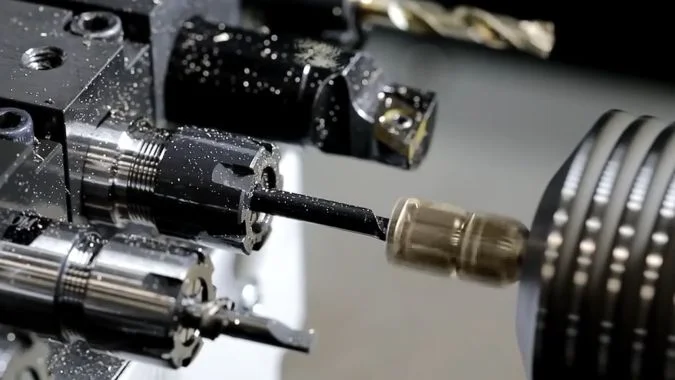
The main idea is simple. The B-axis provides angular positioning, while a fixed high-speed spindle provides tool rotation. The spindle does not need its own servo-driven angle mechanism because the machine axis sets the approach angle.
An expansion holder can carry an independent high-frequency milling spindle. A typical micro-machining spindle may run at 30,000–80,000 rpm and have runout of 1 μm or less9. This speed range is useful for small cutters used on Torx slots, angled holes, narrow grooves, and micro-contours.
The CNC program indexes the B-axis, starts the external spindle, and coordinates movement with the linear axes. This arrangement can reduce tool changes and manual angle adjustments. It can also free other tool positions when one spindle covers several angular approaches.
| Configuration | Angular control | Typical speed | Best use |
|---|---|---|---|
| Fixed live tool | Fixed by holder geometry | Low to medium | Repeated features at one angle |
| Servo-angle live tool | Built into the tool attachment | Varies | Flexible, high-value machining |
| B-axis with standard spindle | Provided by the machine axis | Medium to high | Multi-angle general machining |
| B-axis with high-frequency spindle | Provided by the machine axis | 30,000–80,000 rpm | Micro-holes, slots, and fine contours |
When Is an Angled Live Tool Still Necessary?
A high-frequency spindle is designed mainly for light cutting. Its small motor and tool interface may not provide enough torque for heavy roughing, large drills, or deep slots. Its extended overhang can also reduce rigidity. These limits become more important when hard materials and large cutting depths are involved.
An integrated B-axis power tool remains useful when a process needs high torque and continuous multi-axis movement. Complex spiral milling, deep material removal, and demanding curved-surface machining may require a more rigid driven tool arrangement. The machine structure, spindle bearing design, holder length, and cutting force must all be considered.
The B-axis should therefore be treated as a way to reduce dependence on costly angled holders, not as a universal physical replacement. For indexed angled holes, shallow slots, multi-face milling, and many micro-medical features, a standard or high-frequency spindle may provide a lower-cost solution. For heavy cutting, the more rigid attachment may remain necessary.
What Level of Precision Can Swiss-Type Lathe Achieve with the B-Axis Functionality?
Micron-level specifications can be misleading without stable tooling and temperature control. A machine specification alone cannot guarantee the final tolerance of a medical implant.
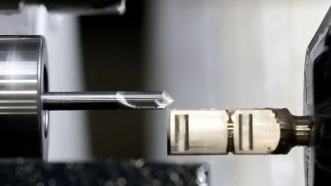
A capable B-axis Swiss lathe can provide linear positioning near 0.003 mm and repeatability near 0.001 mm. B-axis indexing may reach 0.001°, while validated part tolerances commonly fall within ±0.005 mm and can approach ±0.002–0.003 mm for suitable micro-parts.
Which Precision Indicators Matter Most?
Positioning accuracy describes how closely an axis reaches a commanded location. Repeat positioning accuracy describes how consistently it returns to that location. Both figures matter, but neither one equals finished-part accuracy. The final result also depends on guide-bush alignment, bar quality, spindle runout, cutting force, tool wear, coolant condition, and thermal stability.
B-axis angular error also creates larger linear error as the cutting point moves farther from the axis center. Tool overhang must therefore remain controlled. A short and rigid tool assembly supports better feature location and surface quality.
| Precision indicator | Typical high-performance value | Practical meaning |
|---|---|---|
| Linear-axis positioning | About 0.003 mm | Ability to reach a programmed position |
| Linear-axis repeatability | About 0.001 mm | Ability to repeat the same movement |
| B-axis indexing accuracy | About 0.001° | Angular positioning of the tool unit |
| B-axis repeatability | About ±0.0005° to ±0.001° | Consistency across repeated indexing |
| Stable batch tolerance | About ±0.005 mm | Common production target under control |
| High-precision micro-part tolerance | About ±0.002–0.003 mm | Possible with a capable and validated process |
How Can ±0.003 mm Be Maintained in Production?
Stable micron-level machining requires more than buying a machine with a suitable specification. The bar must have controlled diameter, straightness, and material condition. The guide bush must match the bar and provide support without excessive friction. The cutting tools must have low runout and predictable wear.
Temperature also affects the result. Machine warm-up, coolant control, and shop temperature reduce thermal movement. Tool-life limits should be based on measured feature drift instead of visible tool failure. In-process probing or regular inspection can detect movement before a batch exceeds tolerance.
Medical manufacturers must also validate burr control, cleaning, surface finish, and traceability10. Dimensional accuracy alone does not prove that an implant is acceptable. The process should include suitable inspection methods, calibrated equipment, controlled handling, and documented quality checks.
Conclusion
A B-axis Swiss lathe combines angular machining, guide-bush support, dual-spindle production, and one-clamping completion to produce complex medical implants with high precision, consistency, and lower handling risk.
-
"Orthopedic hardware and equipment for the beginner. Part 2", https://pmc.ncbi.nlm.nih.gov/articles/PMC3215475/. Orthopedic implant literature documents that small-fragment and mini-fragment bone screws range from approximately 1.5 mm to 4.0 mm in diameter, with overall lengths commonly between 4 mm and 30 mm, requiring sub-millimeter precision in thread profiles, drive recesses, and locking features. Evidence role: general_support; source type: education. Supports: dimensional ranges of small medical bone screws used in orthopedic applications. ↩
-
"6 Precision Machining Challenges SOLVED with Smart DFM", https://www.phi2.com/blog/6-precision-machining-challenges-solved-with-smart-dfm/. Manufacturing research indicates that small-scale features such as drive recesses, cross-holes, and variable thread forms in medical implants present challenges including tool access limitations, burr formation, dimensional variation from cutting forces, and difficulty maintaining surface integrity across multiple feature types in a single workpiece. Evidence role: mechanism; source type: research. Supports: technical challenges associated with machining complex micro-features in medical implants. ↩
-
"Swiss-Type Automatic Lathe | CNC Machines New York", https://starcnc.com/products/. Machine tool industry standards show that rotary B-axis configurations commonly range from limited indexing systems (±30° to ±45°) to full-rotation capable designs, with continuous machining implementations typically offering ±90° to ±120° of angular travel depending on machine architecture and collision avoidance requirements. Evidence role: statistic; source type: institution. Supports: typical angular motion ranges for rotary axes in precision CNC machines. Scope note: Actual range varies significantly by manufacturer and machine model ↩
-
"Vibration Suppression with Use of Input Shaping Control in …", https://pmc.ncbi.nlm.nih.gov/articles/PMC8951330/. Machining mechanics research demonstrates that guide bushing support positioned close to the cutting zone significantly reduces workpiece deflection and vibration, particularly important for slender parts with length-to-diameter ratios exceeding 3:1, where unsupported cutting can result in dimensional errors, chatter, and poor surface finish. Evidence role: mechanism; source type: research. Supports: the mechanical principle of guide bush support in reducing workpiece deflection during small-diameter machining. ↩
-
"Deflection and Precision in Swiss Metal CNC Machining", https://metalcutting.com/knowledge-center/deflection-precision-cnc-swiss-machining/. Machine tool dynamics research shows that support structures positioned near the cutting zone reduce the effective unsupported length of slender workpieces, thereby increasing the natural frequency and stiffness of the workpiece-machine system, which significantly decreases deflection under cutting forces and suppresses regenerative chatter vibration. Evidence role: mechanism; source type: research. Supports: the mechanical principle by which guide bushing support reduces deflection and vibration in slender workpieces. ↩
-
"Datum in GD&T: Definition, Features, and Types …", https://www.xometry.com/resources/machining/datum-in-gd-t/. Manufacturing engineering principles establish that each workpiece repositioning introduces potential datum reference errors through fixture tolerances, clamping variations, and alignment uncertainties, with error accumulation becoming particularly significant in tight-tolerance applications where feature relationships must be maintained within microns. Evidence role: mechanism; source type: education. Supports: the principle of datum transfer and error accumulation in multi-setup manufacturing. ↩
-
"Safety of Metals and Other Materials Used in Medical …", https://www.fda.gov/medical-devices/products-and-medical-procedures/safety-metals-and-other-materials-used-medical-devices. Medical device materials science literature identifies titanium alloys (particularly Ti-6Al-4V), cobalt-chromium alloys, stainless steel (316L), and biodegradable polymers and magnesium alloys as principal material categories for orthopedic and dental implants, selected based on biocompatibility, mechanical properties, corrosion resistance, and specific clinical applications. Evidence role: general_support; source type: education. Supports: common material categories used in medical implant manufacturing. ↩
-
"Efficient scheduling to reduce setup times and increase …", https://dspace.mit.edu/entities/publication/76066a30-586f-4948-9df9-9c7499a3e196. Manufacturing efficiency studies indicate that consolidating multi-setup operations into single-setup processes typically yields cycle time reductions of 20–40%, with greater improvements (2–5× productivity gains) observed in cases where part handling, fixturing complexity, and setup time constitute significant portions of the original production cycle. Evidence role: statistic; source type: research. Supports: productivity gains from reducing setup operations in precision manufacturing. Scope note: Actual gains are highly dependent on part complexity, original process design, and operation balance ↩
-
"(PDF) An Ultra-high Speed Spindle for Micro-milling", https://www.academia.edu/20318396/An_Ultra_high_Speed_Spindle_for_Micro_milling. Precision machining literature documents that high-frequency motorized spindles designed for micro-machining operations typically operate in the 30,000–100,000 rpm range, with precision-grade units achieving axial and radial runout below 1–2 μm through precision bearing systems and balanced rotor assemblies. Evidence role: statistic; source type: research. Supports: performance specifications of high-frequency spindles used in micro-machining applications. ↩
-
"Process Validation: General Principles and Practices", https://www.fda.gov/files/drugs/published/Process-Validation–General-Principles-and-Practices.pdf. Medical device regulations, including FDA Quality System Regulation (21 CFR 820) and ISO 13485, require manufacturers to validate manufacturing processes through documented evidence that procedures consistently produce devices meeting predetermined specifications, including dimensional accuracy, surface characteristics, cleanliness, and complete traceability throughout production. Evidence role: expert_consensus; source type: government. Supports: regulatory requirements for process validation in medical device manufacturing. ↩

Chris Lu
Leveraging over a decade of hands-on experience in the machine tool industry, particularly with CNC machines, I'm here to help. Whether you have questions sparked by this post, need guidance on selecting the right equipment (CNC or conventional), are exploring custom machine solutions, or are ready to discuss a purchase, don't hesitate to CONTACT Me. Let's find the perfect machine tool for your needs.