

Why Are Holes Milled on a CNC Milling Machine Out of Tolerance?
A milled hole can fail inspection despite a correct programmed diameter. Repeated offset changes waste parts, so the investigation must separate size errors from shape errors.
CNC-milled holes can exceed tolerance because of axis-motion errors, tool deflection, spindle or holder runout, workpiece movement, thermal changes, or incorrect offsets. Oval holes need checks of X/Y circular interpolation and cutting stability. Reliable measurement should establish the error before mechanical repairs or parameter changes begin.
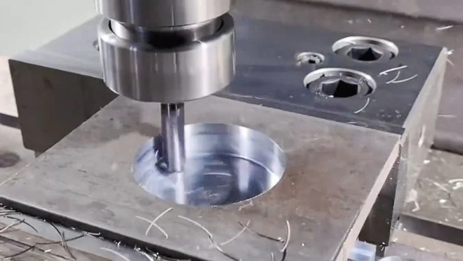
A circular hole is produced by more than the diameter entered in the program. The X and Y axes move together, the cutter removes material under load, and the fixture holds the workpiece in shape. The finished wall records the combined result. That makes the actual hole profile the starting point for investigation.
Why Does a CNC Mill Cut Oval Holes Instead of Round Ones?
An oval hole can prevent correct assembly, and diameter compensation may leave the shape error unchanged. The investigation needs to separate motion errors from cutting and clamping effects.
A CNC mill cuts an oval hole when the cutting edge follows a distorted path or the workpiece changes shape. Backlash, axis squareness errors, unequal axis response, tool deflection, and clamping distortion are possible causes. Spindle runout can affect accuracy, but an oval alone does not prove spindle damage.

The error must be defined before adjustments begin
An oversized circular hole, an oval hole, and a correctly sized hole in the wrong position are different problems. Tool radius compensation mainly changes size. A work offset changes the programmed location. Neither adjustment establishes the cause of an irregular profile.
The inspector should check clean surfaces with calibrated equipment suited to the tolerance. Measurements at several depths help reveal taper or changes along the wall. Several diameter readings can flag ovality, but a roundness tolerance needs an appropriate profile measurement.
Mechanical condition comes before compensation
Wear or looseness in ballscrews, support bearings, nuts, and couplings can allow lost motion.1 Uneven friction can also disturb an axis during reversal. The resulting profile may contain flats or steps instead of a smooth oval.
| Possible cause | Effect on the hole | Useful initial check |
|---|---|---|
| Transmission clearance | Lost motion near axis reversal | Reversal measurements and mechanical inspection |
| X/Y geometry or response error | Distorted circular path | Circular-motion testing |
| Flexible tool or uneven allowance | Changing wall position under load | Controlled finishing-cut comparison |
| Clamping distortion | Shape changes after fixture release | Measurements before and after unclamping |
| Spindle or holder problems | Unequal tooth loading and unstable cutting | Runout, seating, and bearing checks |
Spindle runout can change the effective cutting diameter and tooth loading without creating a fixed oval. The measured hole shape should guide further spindle checks.
Thin walls can also spring back after unclamping.2 The inspection should record the clamping state and part temperature. Mechanical defects need correction before compensation is considered. Servo adjustments should follow measured evidence and the machine builder’s procedure.
What Can the Oval’s Orientation Reveal About the Error?
The oval’s direction can narrow the investigation, but treating it as proof can lead to unnecessary repairs. Direction, repeatability, and travel direction need comparison.
The oval’s orientation indicates which error patterns deserve testing. A diagonal oval can suggest squareness error or unequal servo response. An oval aligned with X or Y can suggest unequal axis scaling. Clockwise and counterclockwise motion tests help distinguish these patterns from reversal defects and cutting effects.
The reference must remain tied to the machine axes
The inspection record should identify the machine’s X and Y directions on the part. An orientation described only as horizontal or vertical can become misleading after the workpiece is removed or turned.
The complete profile matters. A smooth oval, a flattened quadrant, and a short spike are different clues. Two perpendicular diameter readings can miss a diagonal distortion.
The following patterns are most useful in a measured circular-motion test without cutting load.
| Measured pattern | Possible explanation | Supporting comparison |
|---|---|---|
| Diagonal oval with the same orientation in both travel directions | X/Y squareness error | Similar distortion at different feed rates |
| Diagonal oval whose long axis switches between travel directions | Unequal servo response | Error changes with contouring speed |
| Smooth oval aligned with X or Y | Unequal axis scaling or positioning | Independent axis travel measurements |
| Steps or spikes near quadrant transitions | Lost motion, friction, or reversal response | Repeated reversal tests |
| Changing or irregular distortion | Combined errors or unstable test conditions | Repeatability and setup checks |
A ballbar trace and a cut hole provide different evidence
A ballbar measures changes in radius during commanded circular motion.3 Clockwise and counterclockwise runs help separate geometric effects from direction-dependent motion errors.4
A cut hole also includes tool forces and workpiece deformation. Reversing the cutting direction changes the engagement between tool and material, so that comparison alone cannot isolate servo behavior.
Mixed errors can also shift the oval away from the usual orientations. A single 45-degree pattern should not trigger guideway adjustment or servo tuning without further measurements.
How Can Tool Deflection Be Separated from Axis-Motion Error?
Tool bending and axis errors can produce similar rejected holes. Replacing tools without comparison tests can miss the cause, so cutting load and machine motion need separate checks.
Tool deflection can be investigated through controlled changes in tool stiffness and cutting load. X/Y motion needs an independent circular-path test without cutting. Static tool and spindle runout checks assess another error source; subtracting those readings does not measure tool deflection or axis contouring error.

A controlled cutting comparison tests the effect of load
Tool deflection is elastic bending under cutting force.5 A long tool can show little static runout and still bend during machining.
A useful comparison uses equivalent test holes with the same material, workholding, spindle speed, and finishing allowance. One trial can use an equivalent cutter with shorter overhang. Another can use a smaller, consistent radial finishing allowance. Each trial should change one factor.
| Comparison | Result that matters | What it supports |
|---|---|---|
| Shorter tool overhang | Roundness improves | Tool stiffness contributes to the error |
| Lower radial finishing load | Profile error decreases | Load-dependent deformation contributes |
| Circular-motion test without cutting | Similar directional error remains | Machine motion contributes independently |
| Measurements before and after unclamping | Hole shape changes | Workholding or stress release contributes |
These results guide the diagnosis; they do not identify every component involved. A lighter cut also reduces forces on the spindle, fixture, and machine structure. A good unloaded motion test does not exclude movement that appears only under cutting load.
Runout checks answer a separate question
The assembled cutter and holder need inspection for dirt, damage, poor seating, and uneven cutting-edge projection. A spindle check can use the specified taper surfaces and a precision test bar, with manual rotation under the machine builder’s service procedure.
The measurements should use defined contact locations. Test-bar accuracy and seating also affect the result.
The tool assembly reading and spindle reading are combined geometric measurements. Their difference cannot be treated as a direct measurement of X/Y motion error. A larger tool-assembly reading justifies further checks of the cutter, collet, and holder.
Independent circular-motion testing should use a relevant table location, test radius, and feed range. The results can then be assessed alongside the cutting trials. Differences in test geometry and loading mean the two results should not be directly subtracted.
Why Can a Hole Become Less Round as Feed Rate Increases?
A faster feed can reduce cycle time and increase rejected holes. A controlled feed comparison helps determine whether cutting forces or axis response limit accuracy.
Higher feed can worsen hole roundness by increasing cutting forces, tool deflection, vibration, and unequal axis following errors. At unchanged spindle speed, feed per tooth also increases. A slower cut may improve the result, but only separate cutting and motion tests can identify the dominant cause.
Cutting load and axis acceleration increase for different reasons
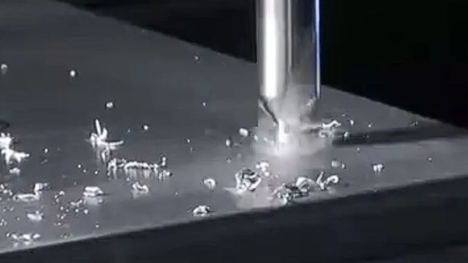
At constant spindle speed and tool geometry, a higher feed usually increases chip load.6 Greater forces can bend a slender cutter or move a poorly supported wall. Uneven stock around the hole can make that deformation vary around the circumference.
Vibration can add waviness or local defects. A higher feed does not always cause chatter, and a lower feed does not correct every vibration problem.
Faster circular motion also requires greater axis acceleration at the same path radius.7 Unequal responses from X and Y can then produce greater contour error. Matching the numeric gain settings alone does not establish matched behavior because the axes can have different mechanical characteristics.
| Result during comparison | Likely area for further investigation |
|---|---|
| Cutting accuracy improves with lower load, but unloaded motion stays consistent | Tool, spindle, fixture, or workpiece stiffness |
| Unloaded circular-path error increases with feed | Axis response, friction, or control behavior |
| Shorter overhang improves the same feed-rate trial | Tool deflection |
| Shape changes after unclamping | Fixture deformation or stress release |
| Dimensions drift during a production run | Temperature, wear, and process consistency |
The programmed feed must suit internal circular milling
The tool centre follows a smaller circle than the hole wall.8 Internal circular milling needs the correct relationship between tool-centre feed and feed at the machined contour. The programmer should verify how the CAM system and control handle that conversion.
The finishing trial should use consistent allowance and a feed within the tool supplier’s working range. An extremely light cut can introduce rubbing instead of stable cutting.
Thermal effects need their own comparison. Uneven heating can distort a workpiece, but uniform expansion mainly changes size.9 Measurements taken at a consistent temperature help prevent thermal drift from being mistaken for a feed-related roundness error.
Conclusion
Reliable hole correction starts with the measured profile. Orientation, controlled cutting trials, and independent motion tests help identify the cause before offsets or servo settings change.
-
"Understanding and Managing Backlash in Ball Screws", https://www.wyballscrew.com/post/the-silent-enemy-understanding-and-managing-backlash-in-ball-screws. Mechanical engineering references on precision machine design identify clearance in ballscrew nuts, bearing preload loss, and coupling backlash as mechanisms that permit lost motion during axis reversal. Evidence role: mechanism; source type: education. Supports: that wear and clearance in ballscrew assemblies and couplings introduce lost motion that degrades positioning accuracy. ↩
-
"Automated fixture design for a rapid machining process", https://dr.lib.iastate.edu/bitstreams/e0e6f247-4aec-4cef-a373-c1e64fbea6f4/download. Manufacturing research on workholding demonstrates that clamping forces cause elastic deformation in workpieces, especially in thin-walled or compliant geometries, and that removal of these forces allows elastic recovery that can alter the final part geometry measured in the free state. Evidence role: mechanism; source type: research. Supports: that clamping forces elastically deform workpieces, particularly thin-walled features, and that these deformations recover when fixtures are released, changing measured dimensions. ↩
-
"Ballbar testing explained", https://www.renishaw.com/en/ballbar-testing-explained–6818?srsltid=AYCX9vIIAv4B1OY6tNqK2LuRcxf-HdxjfLR5jIKVzHiYYEcYinOHKPeX. A ballbar is a telescoping gauge with precision spheres at each end, used to measure the radial error of a machine tool’s circular interpolation by tracking length changes as the machine executes a circular path. Evidence role: definition; source type: encyclopedia. Supports: that a ballbar (or double ball bar) is a telescoping precision instrument used to measure radial deviation during programmed circular motion. ↩
-
"Information Model for Machine-Tool-Performance Tests – PMC", https://pmc.ncbi.nlm.nih.gov/articles/PMC4862811/. Machine tool testing standards describe bidirectional circular interpolation tests as a method to separate geometric errors such as squareness, which produce consistent patterns regardless of direction, from dynamic errors like servo mismatch or friction that vary with motion direction. Evidence role: general_support; source type: institution. Supports: that comparing clockwise and counterclockwise circular tests helps distinguish geometric errors (which appear similarly in both directions) from servo and friction effects (which may reverse or change). Scope note: Standards describe the test method but may not explicitly detail every error-separation principle mentioned ↩
-
"What Is Tool Deflection and How Can You Prevent It?", https://taigtools.com/blog/tool-deflection/. Machining mechanics texts describe cutting tool deflection as elastic bending governed by beam theory, where deflection increases with cutting force and tool overhang while decreasing with tool diameter and material stiffness. Evidence role: mechanism; source type: education. Supports: that cutting tools behave as cantilever beams and undergo elastic deflection proportional to cutting forces and inversely proportional to tool stiffness. ↩
-
"Feed Per Tooth [Fz]", https://www.machiningdoctor.com/glossary/feed-per-tooth/. Machining textbooks define chip load as the feed rate divided by spindle speed and number of cutting edges, establishing that feed rate increases at constant spindle speed directly increase the material removed per tooth and the resulting cutting forces. Evidence role: mechanism; source type: education. Supports: that chip load (feed per tooth) equals table feed rate divided by the product of spindle speed and number of teeth, so increasing feed at constant speed increases chip load proportionally. ↩
-
"Circular motion", https://en.wikipedia.org/wiki/Circular_motion. Kinematics principles establish that circular motion at constant radius requires centripetal acceleration proportional to the square of velocity, meaning that doubling the feed rate quadruples the required axis acceleration. Evidence role: mechanism; source type: education. Supports: that centripetal acceleration in circular motion equals velocity squared divided by radius, so higher feed rates require proportionally greater axis accelerations. ↩
-
"Mill Toolpath Guide", https://www.purdue.edu/bidc/resources/metal-working/mill-toolpath-guide/. CNC programming references explain that for internal circular milling, the commanded tool center path has a radius equal to the desired hole radius minus the cutter radius, requiring appropriate tool radius compensation or offset programming. Evidence role: mechanism; source type: education. Supports: that in internal milling operations, the tool center path radius equals the hole radius minus the tool radius. ↩
-
"Dimensional Accuracy of Different Three-Dimensional Printing …", https://pmc.ncbi.nlm.nih.gov/articles/PMC11279353/. Thermal mechanics principles show that uniform temperature change in an unconstrained body produces isotropic expansion that scales all dimensions proportionally, whereas temperature gradients generate internal stresses and non-uniform strain that distort the original geometry. Evidence role: mechanism; source type: education. Supports: that uniform temperature change produces proportional dimensional expansion without shape change, while temperature gradients create differential expansion that causes bending and distortion. ↩

Chris Lu
Leveraging over a decade of hands-on experience in the machine tool industry, particularly with CNC machines, I'm here to help. Whether you have questions sparked by this post, need guidance on selecting the right equipment (CNC or conventional), are exploring custom machine solutions, or are ready to discuss a purchase, don't hesitate to CONTACT Me. Let's find the perfect machine tool for your needs.