

Why Do Tapping Centers with the Same Max RPM Have Different Tapping Cycle Times?
A speed rating can make two tapping centers look equally fast. Timing the stages of a tapping cycle shows which machine completes the part sooner.
Tapping centers with the same maximum RPM can have different cycle times because their spindles accelerate, brake, and reverse at different rates. Usable tapping speed, synchronized Z-axis motion, and travel between holes also affect cycle time. Short holes may leave little time at the commanded speed.
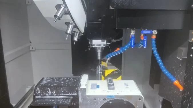
Spindle speed is easy to compare on two specification sheets. The tap follows a separate set of limits because the spindle and Z axis move together through the thread. A fair comparison starts by identifying which speed the supplier quotes and which speed the test part can actually use under its production conditions.
What Is the Difference Between Maximum Spindle RPM and Maximum Tapping RPM?
A spindle rating can overstate the speed available for a tapping job. The machine specification and the programmed cycle give the relevant limits.
Maximum spindle RPM is the spindle’s rated speed ceiling. Maximum tapping RPM is the machine’s specified ceiling for synchronized tapping in a given configuration. The usable speed for a particular hole also depends on thread pitch, tap geometry, workpiece material, and chip evacuation.
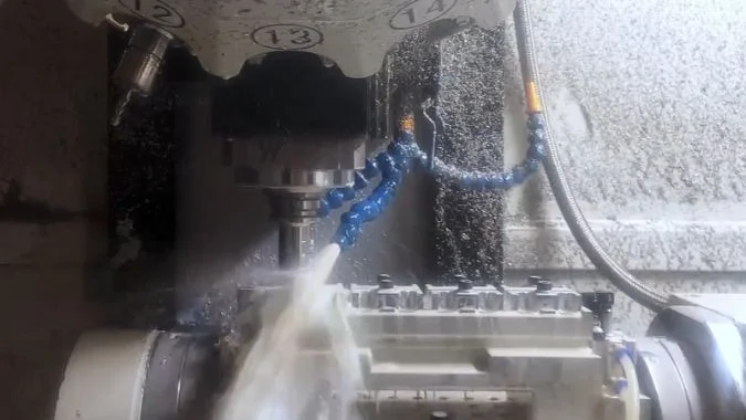
Rigid tapping ties spindle rotation to Z-axis travel
In rigid tapping, the control coordinates Z-axis position with spindle angle.1 For a single-start thread, the Z axis advances one pitch per spindle revolution.2 A coarse pitch requires more Z-axis travel per revolution, so it demands a higher feed at the same RPM.
The axes must maintain that relationship during acceleration and reversal as well as steady cutting. Spindle inertia, available torque, and the control’s response affect how quickly the machine can complete those transitions.3 Poor synchronization can load the tap or damage the thread.4
| Speed figure | What it represents | Where to check it |
|---|---|---|
| Maximum spindle RPM | Rated spindle speed for the configuration | Machine specification |
| Maximum tapping RPM | Rated limit for the synchronized cycle | Tapping specification and control options |
| Programmed tapping RPM | Speed selected for the tap and job | CNC program and tap supplier data |
| Actual RPM during the hole | Speed achieved during that stroke | Spindle speed trace or control diagnostics |
A short stroke can limit the speed reached
A tapping center can have enough spindle speed for the job and still spend most of a short stroke accelerating and braking.5 Another machine with the same spindle ceiling may reach the commanded tapping speed earlier and begin its return sooner.
Rapid moves to the approach plane and between holes also take time. On short moves, axis acceleration determines how much of the rated rapid speed the machine reaches. The synchronized portion inside the thread follows the tap’s lead.
How Do Thread Depth and Tapping RPM Affect the Time the Tap Spends Cutting?
A deeper hole takes longer to tap, but the depth on the drawing can differ from the cutting stroke. The estimate needs the actual travel and pitch.
At constant RPM, cutting time increases in proportion to the engaged stroke and decreases as tapping RPM rises. For a single-start thread, the ideal cutting time in seconds is 60 × engaged stroke in millimeters ÷ (pitch in millimeters × tapping RPM).

Pitch converts RPM into feed
For a single-start metric thread, the synchronized feed in mm/min equals pitch in mm multiplied by RPM.6 The cutting stroke divided by that feed gives time in minutes. Multiplying by 60 converts the result to seconds.
The following example uses an M10 × 1.5 tap and a 20 mm engaged cutting stroke.
| Tapping speed | Synchronized feed | Ideal cutting time |
|---|---|---|
| 500 RPM | 750 mm/min | 1.60 s |
| 800 RPM | 1,200 mm/min | 1.00 s |
| 1,000 RPM | 1,500 mm/min | 0.80 s |
| 1,500 RPM | 2,250 mm/min | 0.53 s |
At 1,000 RPM, extending the stroke from 20 mm to 30 mm raises the ideal cutting time from 0.80 to 1.20 seconds. The extra 10 mm requires 50% more cutting travel at the same feed.
The programmed depth and cutting stroke can differ
The drawing may specify full thread depth. The tap’s lead chamfer can require additional travel to produce that depth.7 A cycle can also begin its synchronized feed at a reference plane above the face. That approach distance belongs in the cycle estimate, and the engaged stroke determines the cutting estimate.
The tap supplier’s cutting data gives a starting speed for the material and tool. Hole type, chip clearance, and lubrication affect the usable speed. The table represents steady travel. An actual stroke can spend part of its length below the commanded RPM as the spindle accelerates or brakes.
How Much Time Do Spindle Deceleration and Reversal Add to Each Hole?
Repeated reversals can account for a large share of a short hole cycle. A spindle and Z-axis trace shows how long the transition takes.
Reversal time depends on the actual forward speed, braking response, any programmed dwell, and acceleration into reverse. A trace can measure the interval from the start of braking to a defined point on the return. The same timing points make comparisons between tapping centers meaningful.
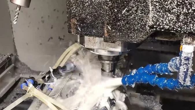
The speed trace shows each part of the reversal
The spindle slows near the programmed bottom, and Z slows with it. The control then coordinates reverse rotation with upward travel. A higher return speed can require a longer acceleration interval, depending on the spindle and drive.
An illustrative trace gives the following timestamps for one hole.
| Event | Example timestamp | Elapsed time |
|---|---|---|
| Forward braking starts | 2.00 s | Start of measurement |
| Spindle reaches zero speed | 2.18 s | 0.18 s from braking start |
| Spindle reaches steady reverse speed | 2.35 s | 0.17 s from zero speed |
| Total reversal interval | 2.00 to 2.35 s | 0.35 s |
A short return stroke may end before reverse speed settles. In that case, the test can use agreed Z positions on entry and exit around the reversal to define a repeatable timing window.
The tap travels during braking and reverse acceleration
The tap can still move down while braking and start moving up while reverse speed builds.8 The time added over a constant-speed estimate is the measured interval minus the ideal travel time for the same downward and upward distances.
A spin-up figure from rest to maximum spindle RPM covers a different speed range from a tapping reversal.9 A matched hole test captures the effect of the actual tap, commanded speeds, and machine response. An extra 0.50 seconds per hole amounts to 8 minutes and 20 seconds over 1,000 holes.10
How Much Time Can a Faster Tap Retract Save Across a Full Part?
A faster return can save time on every threaded hole. The engaged stroke, thread pitch, and reverse RPM determine the starting estimate.
The ideal part saving equals the time saved on each synchronized retract multiplied by the number of identical holes. An M3 × 0.5 tap retracting 10 mm at 6,000 RPM instead of 3,000 RPM saves 0.20 seconds at constant speed, or 20 seconds across 100 holes.
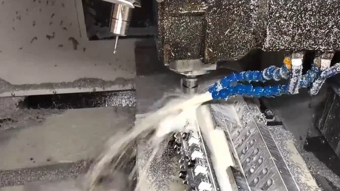
Reverse RPM sets the synchronized return feed
The tap must follow the thread on the way out.11 For a single-start metric thread, the ideal retract time in seconds equals 60 × synchronized return distance ÷ (pitch × reverse RPM).
For the M3 × 0.5 example, the synchronized return distance is 10 mm. The cutting speed and entry settings stay the same in both cases.
| Return setting | Synchronized return feed | Ideal time per hole | Ideal time across 100 holes |
|---|---|---|---|
| 3,000 RPM | 1,500 mm/min | 0.40 s | 40 s |
| 6,000 RPM | 3,000 mm/min | 0.20 s | 20 s |
| Difference | 0.20 s | 20 s |
A full part trial measures the production saving
Reverse acceleration can consume much of a short return. The saving can shrink when the cycle needs more time to reach the higher speed. A longer synchronized return gives the machine more distance to benefit from the higher setting.
The control and spindle configuration determine which return speeds are available. A comparison should use the same tap, entry RPM, thread depth, and clearance planes. Each hole group needs its own calculation if the part uses several thread pitches or depths.
The measured part cycle should include positioning, approach travel, and tool changes. Each tool change counts when it occurs, and a single tap may serve an entire hole pattern. Thread inspection confirms that the faster cycle still meets the same acceptance criteria.12
Conclusion
Matched hole tests reveal how much cutting, reversal, synchronized retract, and positioning contribute to tapping cycle time. Part timing and thread inspection verify the production gain.
-
"Coordination of Slow Waves With Sleep Spindles Predicts …", https://pmc.ncbi.nlm.nih.gov/articles/PMC6084745/. Rigid tapping is a CNC machining method in which the machine control synchronizes Z-axis linear motion with spindle rotation to maintain precise thread pitch without relying on a tension-compression holder. Evidence role: definition; source type: encyclopedia. Supports: the definition and mechanism of rigid tapping in CNC machining. ↩
-
"Screw thread", https://en.wikipedia.org/wiki/Screw_thread. In a single-start thread, the lead equals the pitch, meaning the thread advances axially by one pitch distance for each complete revolution of the threaded component. Evidence role: mechanism; source type: encyclopedia. Supports: the geometric relationship between thread pitch and axial advance in single-start threads. ↩
-
"Integrated Design of Spindle Speed Modulation and Cutting …", https://pmc.ncbi.nlm.nih.gov/articles/PMC8587005/. Spindle acceleration capability depends on the moment of inertia of rotating components, available motor torque, and the bandwidth of the control system’s position and velocity loops, with higher inertia requiring proportionally greater torque to achieve the same angular acceleration. Evidence role: mechanism; source type: education. Supports: the mechanical and control factors that determine spindle acceleration and deceleration performance. ↩
-
"What are common credit report errors that I should look for …", https://www.consumerfinance.gov/ask-cfpb/what-are-common-credit-report-errors-that-i-should-look-for-on-my-credit-report-en-313/. Synchronization errors in rigid tapping can generate axial forces on the tap that exceed design limits, leading to tap breakage or thread form defects when the mismatch between rotational and linear motion creates interference. Evidence role: general_support; source type: research. Supports: the relationship between synchronization errors and tap or thread damage in rigid tapping. ↩
-
"Appropriate Acceleration Rate for CNC Machine Tools?", https://www.practicalmachinist.com/forum/threads/appropriate-acceleration-rate-for-cnc-machine-tools.345692/. In short-stroke machining operations, acceleration and deceleration phases can account for the majority of cycle time when the programmed travel distance is insufficient for the axis to reach and maintain commanded velocity. Evidence role: general_support; source type: research. Supports: the proportion of cycle time consumed by acceleration and deceleration in short-stroke operations. Scope note: This applies to general short-stroke operations; specific percentages vary with stroke length, acceleration rates, and commanded speeds. ↩
-
"Free Machine Shop Tap Feed Calculators", http://janproducts.com/Tap_Feed_Calculator.html. The required feed rate for rigid tapping of a single-start thread is calculated as the product of thread pitch and spindle speed, ensuring that the tool advances exactly one pitch distance per revolution to match the thread geometry. Evidence role: mechanism; source type: education. Supports: the mathematical relationship between thread pitch, spindle speed, and required feed rate in synchronized tapping. ↩
-
"Threads and", https://www.deanza.edu/dmt/documents/books/egd_lamit/EGD_Chapter_17.pdf. Taps feature a lead chamfer that gradually introduces cutting edges over several threads; to achieve full thread depth at the hole bottom, the tap must travel beyond the nominal depth by a distance related to the chamfer length, typically 2-5 thread pitches depending on chamfer design. Evidence role: mechanism; source type: other. Supports: the relationship between tap lead chamfer geometry and required tapping depth. Scope note: Specific chamfer lengths vary by tap design and manufacturer specifications. ↩
-
"Rigid Tapping with New Motor and VFD (DIY CNC Mill …", https://www.youtube.com/watch?v=WwvvC96PKz8. During rigid tapping reversal, the Z-axis continues synchronized motion throughout spindle deceleration and reverse acceleration phases, with the tool moving downward at decreasing velocity during braking and upward at increasing velocity during reverse spin-up to maintain thread pitch relationship. Evidence role: mechanism; source type: education. Supports: the continued motion of synchronized axes during spindle deceleration and reverse acceleration. ↩
-
"Determination of vibration characteristic in automatic tapping …", https://pmc.ncbi.nlm.nih.gov/articles/PMC12066723/. Spindle acceleration performance varies with operating conditions; acceleration from rest to maximum speed involves a different torque-speed profile and thermal state than reversal during tapping, where the spindle decelerates through zero and accelerates in the opposite direction within a narrower speed range. Evidence role: general_support; source type: research. Supports: the difference in acceleration characteristics between starting from rest and reversing direction. Scope note: Specific performance differences depend on spindle design, motor characteristics, and control parameters. ↩
-
"Cycle Time Reduction: Optimizing Manufacturing Efficiency", https://www.jitbase.com/blog/cycle-time-reduction-optimizing-manufacturing-efficiency. In high-volume manufacturing, reductions in per-unit cycle time accumulate linearly across production quantities, making even sub-second improvements economically significant when multiplied by thousands of parts, affecting throughput, machine utilization, and unit cost. Evidence role: general_support; source type: research. Supports: the production impact of small per-cycle time reductions in high-volume manufacturing. ↩
-
"Withdrawals in retirement | The Thrift Savings Plan (TSP)", https://www.tsp.gov/withdrawals-in-retirement/. During retraction in rigid tapping, the tap must maintain synchronized rotation and linear motion to follow the existing thread form, preventing thread damage or tap binding that would occur if the tool were withdrawn at an incorrect pitch relationship. Evidence role: mechanism; source type: education. Supports: the requirement for synchronized motion during tap retraction. ↩
-
"Digital Thread for Manufacturing", https://www.nist.gov/programs-projects/digital-thread-manufacturing. Manufacturing process changes, including modifications to cycle time or operating parameters, require verification that product quality characteristics continue to meet specifications, as parameter optimization can affect dimensional accuracy, surface finish, and functional performance. Evidence role: general_support; source type: other. Supports: the need for quality verification when manufacturing process parameters are modified. ↩

Chris Lu
Leveraging over a decade of hands-on experience in the machine tool industry, particularly with CNC machines, I'm here to help. Whether you have questions sparked by this post, need guidance on selecting the right equipment (CNC or conventional), are exploring custom machine solutions, or are ready to discuss a purchase, don't hesitate to CONTACT Me. Let's find the perfect machine tool for your needs.