

How to Choose Between Internal Mount-Disc Flange Lathe and External Mount-Flange Lathe?
The wrong mount will not go on the flange. The job then stops at the pipe. Bore access, outer landing, and vibration decide internal or external.
An internal mount-disc flange lathe is the choice when the bore is complete and can be gripped, usually at 50 mm or more. An external-mount flange lathe is the choice when the bore is blocked or too small, or when ship vibration needs a rigid outer clamp.
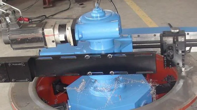
Internal and external flange lathes do not grip the same place. One expands inside the bore. The other clamps the outer rim. A blocked bore, a flush shell, or a shaking deck then makes one of those two mounts impossible. That mounting difference is what separates an internal-disc chuck from an external-mount machine.
What Is the Mounting Difference Between an Internal-Disc Chuck and an External-Mount Flange Lathe?
Internal and external flange lathes grip different places on the flange. The wrong one then cannot be installed. The clamp position is the difference.
An internal-disc chuck expands outward from the flange bore. An external-mount flange lathe clamps inward from the outer rim. Internal uses the bore for centering. External does not need the bore at all.
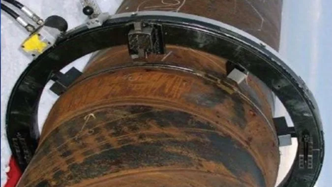
Internal-disc: expand in the bore
An internal-disc chuck puts support legs into the flange bore. The legs expand outward and push on the bore wall. The machine body hangs on the flange face and turns. The bore itself centers the machine, so coaxiality is easier to hold1. Large hollow flanges, pipe ends, and other faces with a complete bore fit this mount. A portable flange facer still needs this clamp to land before the sealing face is cut.
External-mount: clamp the outer rim
An external-mount flange lathe uses outer support legs. The legs grip the flange OD and pull inward. The machine hangs on the flange and does not need floor space. The bore can be blocked, too small, worn, or closed. That state does not stop the mount. On a vibrating deck the outer legs plus a spot-welded anchor also form a stiffer closed loop than an expansion sleeve.
What must be true on the flange
A dirty bore throws an internal mount off center. External mount needs at least 50 mm of clear outer landing. A flange flush with a shell, boxed in by pipes, or recessed leaves the external legs nowhere to sit. That job must use internal mount, or custom long legs. Adjacent pipes that stop the internal legs from expanding force the opposite switch.
| Mount | Clamp location | Needs a usable bore? | Typical fit |
|---|---|---|---|
| Internal-disc | Expands on the bore wall | Yes | Complete, large ID |
| External-mount | Grips the outer rim | No | Blocked, small, or worn bore |
Why Does a Blind or ID-Accessible Flange Favor the Internal Mount-Disc Flange Lathe?
The outer rim of a blind or packed flange is often blocked. External legs then have no landing. The bore is the path that is still open.
A blind or ID-accessible flange favors an internal mount-disc lathe because the outer rim is often blocked by pipes, valves, or a shell. The chuck expands in the bore, matches the bore datum, and needs no outer landing.
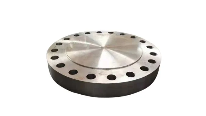
The outer rim is often blocked
Blind flanges and ID-accessible flanges often sit on pipes, valves, or pumps. Adjacent parts then box in the outer rim. External claws cannot reach or cannot grip. An internal-disc chuck expands from the hole and occupies no outer space. Recessed flanges and flanges flush with a shell have the same outer problem. External legs have nowhere to land. Internal mount is then the path that is still open.
The bore is the facing datum
Flange-face work often uses the bore as the positioning datum. Internal expansion starts on that same datum, so datum mismatch stays small. Pipe-end and ID-accessible faces that still have a complete bore match the chuck. A cover with no usable ID is not this case. That job belongs on an outer clamp.
Claw stroke still has to match
Internal expansion force changes with claw position. The effective claw stroke must cover the bore. The flange connection size must also match the machine spindle bore. A correct catalog diameter still will not mount if those two fits fail. Photos of the outer landing and a bore measurement belong in the check before the machine is sent.
| Flange condition | Why internal-disc is favored | When it is not |
|---|---|---|
| OD boxed in by pipes, valves, or a shell | External legs have no landing | OD is clear and the bore is closed |
| ID is complete and accessible | Chuck expands on the bore datum | No usable bore |
| Pipe-end face with ID | Outer space is often tight | Solid cover with no ID |
| Recessed or flush flange | Outer legs cannot sit | Custom long external legs exist |
When Should You Use an Internal Mount-Disc Flange Lathe or an External Mount-Flange Lathe in the Workshop or Onboard a Ship?
Workshop and ship jobs do not share the same mount. A complete bore favors internal. A blocked bore, a shaking deck, or a tight hatch favors external.
An internal mount-disc lathe fits a workshop or ship job when the bore is complete and large. An external-mount lathe fits a blocked bore, a vibrating deck, tight access, or 220 V power. The bore and the site decide, not a fixed rule.
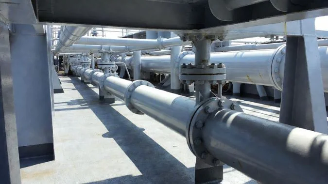
Look at the bore, then the site
There is no universal winner. The bore is the first site check. A complete, regular, accessible bore, especially on a large diameter, favors internal mount. Legs expand from the bore, center themselves, and hold coaxiality for sealing faces and octagonal or RX ring grooves2. A blocked, worn, or closed bore favors external mount. Legs grip the OD. The machine hangs on the flange. A large flange with bore access favors internal. A good outer edge with a blocked bore favors external. A small temporary face repair favors a hand-crank model first.
Inside the workshop
Large flanges with complete bores keep tighter geometry on internal mount. Flatness of 0.05 mm and Ra ≤ 3.23 is a typical internal result on DN50–DN300 process flanges and can meet ASME B16.54. Manifolds and vessel nozzles above DN300 with a complete ID also fit internal. A DN600 face with a complete bore is an internal job. Unevenly worn bores and closed covers go to external. Damage deeper than 30 mm may need extended tool arms5, or a weld build-up before the cut. Below DN300, a blocked bore or a tight shop corner also favors external.
Onboard a ship
Decks and offshore platforms shake. Internal expansion can micro-slip6. External legs on the OD plus a spot-welded anchor hold a stiffer loop7. Internal is not always more precise. On a vibrating job the external closed loop is the more stable mount.
Ship power is often 440 V / 60 Hz or 690 V8. Large internal machines may want 380 V. Many external models run 220 V single-phase after a marine transformer. A model that accepts 220 V ±10% is easier to feed.
Hatches and tower manways can be smaller than the crate. External machines often break down for carrying. A 15 kg hand-crank internal unit9 can go through a pipe corridor or a pump-room corner with no motor and no cable. Dry-dock time is short. External mount can go on, cut, and come off in a day, so a valve does not have to leave the ship for the shop.
| Site / condition | Favored mount | Why |
|---|---|---|
| Complete bore, DN300+ or DN600+ | Internal-disc | Auto-center and coaxiality |
| DN50–DN300, complete bore, shop | Internal-disc | 0.05 mm / Ra ≤ 3.2 typical |
| Blocked or worn bore, workshop | External-mount | OD grip, no ID needed |
| Ship vibration / offshore sway | External-mount | Rigid loop, less micro-slip |
| 220 V only, or no power | External 220 V, or 15 kg hand-crank | Power and access |
| Tight hatch or pipe gallery | External (breaks down) or hand-crank | Passage size |
What Happens if the Flange Bore Is Too Small for the Disc Chuck Range?
A disc chuck that cannot enter the bore will not mount. Forcing internal then eccentric-cuts the face. The clamp method must change.
If the flange bore is too small for the disc chuck range, the first move is external-mount clamping on the outer rim. Smaller claws or an arbor are the backup when internal must stay. The clamping lower limit matters more than the machining upper limit.
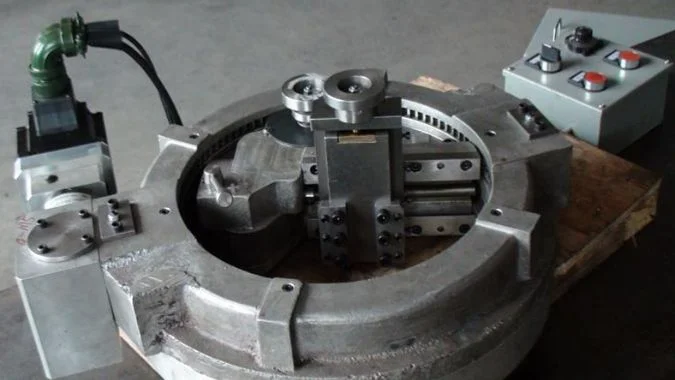
Switch the clamp, do not force the disc
A bore that is too small for the disc chuck cannot take internal expansion. Forcing the chuck then fails to mount, or it grips at the end of claw stroke and the force drops. The first change is external-mount. Regular outer edges let legs or claws grip the OD. Bore size then does not matter. Some machines cut 0–300 mm and clamp about 50–305 mm on the outside10. Those ranges are built for small flanges with blocked or worn bores. The purchase check is whether the clamping-diameter lower limit covers the flange OD. The machining-diameter upper limit is not that check. Emergency small-diameter work can go down to 25.4 mm on a manual external model.
Stay internal only with smaller claws or an arbor
Internal can stay if smaller claws fit, or if an arbor in the spindle taper holds the small bore. Some chucks accept replaceable claws and can shrink the clamp range. Clamping force still changes with claw position. At a small diameter the stroke is near its stop, and grip can decay. That must be confirmed before the job.
Align after the mount
A dial indicator must prove the mount. Runout should stay within 0.05 mm before the cut11. A larger error machines a bell mouth. If the outer edge is also irregular and the bore is still too small, a special fixture or a shop send-out may be the remaining path.
| Option | When it works | What to verify |
|---|---|---|
| External-mount on the OD | Outer edge is regular | Clamping-diameter lower limit covers the OD |
| Smaller claws or a spindle arbor | Internal must stay, and a small ID still exists | Claw stroke and leftover grip at the small diameter |
| Dial-indicator alignment | After any mount | Runout within 0.05 mm before the cut |
| Special fixture or shop send-out | OD is irregular and the bore is still too small | Site conditions, not the catalog upper limit |
Conclusion
The open, large bore takes internal mount. A blocked bore or a shaking deck takes external mount. Landing space must be confirmed before the machine ships.
-
"Research Progress on Precision Tool Alignment Technology …", https://pmc.ncbi.nlm.nih.gov/articles/PMC11509547/. Bore-centered fixturing in rotary machining establishes a common datum between the workpiece reference surface and the cutting tool axis, reducing cumulative positioning error compared to external reference methods. Evidence role: mechanism; source type: research. Supports: the mechanical principle by which bore-centered mounting affects alignment accuracy. Scope note: Actual coaxiality depends on bore condition, expansion force uniformity, and machine rigidity ↩
-
"What is a Ring Type Joint (RTJ) Flange?", https://www.coastalflange.com/blog/what-is-a-ring-type-joint-rtj-flange/. RX and octagonal ring grooves are precision-machined profiles specified in standards such as API 6A for metal ring gaskets in high-pressure applications, requiring accurate groove geometry and surface finish to ensure proper gasket seating and seal integrity. Evidence role: definition; source type: government. Supports: the definition and application of specialized flange groove types. ↩
-
"ASME B16.5 Flange Tolerances Guide | PDF", https://www.scribd.com/document/426755531/Tolerance-as-per-B16-5. ASME B16.5 specifies flange face finish requirements including flatness tolerances and surface roughness values for pressure-containing applications, with typical Ra values ranging from 3.2 to 12.5 μm depending on gasket type and service conditions. Evidence role: general_support; source type: government. Supports: typical flatness and surface finish requirements for flanged connections. Scope note: Standard specifies requirements rather than achievable machining precision ↩
-
"ASME B16.5 Flange Facing Finish", http://www.pipingpipeline.com/asme-b16-5-flg-facing-finish.html. ASME B16.5 establishes dimensional standards and tolerances for pipe flanges and flanged fittings, including specifications for flange face finish, flatness, and surface texture to ensure proper sealing performance in pressure piping systems. Evidence role: definition; source type: government. Supports: the scope and requirements of ASME B16.5 for flange surfaces. ↩
-
"FF120 QuickFace Flange Facing Tool Demo | Hand-Operated …", https://www.youtube.com/watch?v=RETQUDL84tY. Portable flange facing machines typically have standard tool reach limitations in the 20–40 mm range, beyond which extended tool holders or multiple passes become necessary to maintain cutting stability and surface finish quality. Evidence role: general_support; source type: research. Supports: typical depth-of-cut limitations for portable flange machining equipment. Scope note: Actual depth capacity varies significantly by machine model and tool configuration ↩
-
"Fault Diagnosis for Rotating Machinery Using Vibration … – PMC", https://pmc.ncbi.nlm.nih.gov/articles/PMC4934321/. Expansion-type workholding devices rely on radial friction forces that can experience incremental displacement (micro-slip) when subjected to cyclic loading or vibration, as the normal force distribution may vary with dynamic conditions. Evidence role: mechanism; source type: research. Supports: the mechanical behavior of expansion-type fixtures under dynamic loading. Scope note: Actual slip depends on expansion force magnitude, surface conditions, and vibration frequency ↩
-
"The Mechanics of External Fixation – PMC – NIH", https://pmc.ncbi.nlm.nih.gov/articles/PMC2504087/. Closed-loop fixture designs that create continuous load paths through the workpiece perimeter generally exhibit higher structural stiffness than radial expansion systems, as they distribute constraint forces more uniformly and reduce compliance in the clamping mechanism. Evidence role: mechanism; source type: research. Supports: structural principles affecting fixture rigidity in different mounting configurations. Scope note: Actual stiffness depends on specific geometry, material properties, and anchor implementation ↩
-
"46 CFR Part 110 Subpart 110.10", https://www.ecfr.gov/current/title-46/chapter-I/subchapter-J/part-110/subpart-110.10. Maritime electrical standards specify common shipboard voltage systems including 440V three-phase for medium vessels and 690V for larger installations, though actual voltages vary by vessel size, flag state, and construction era. Evidence role: general_support; source type: institution. Supports: standard voltage levels used in marine electrical systems. Scope note: Voltage standards vary by vessel type, age, and regulatory jurisdiction ↩
-
"Manual Flange Facer | Portable Hand-Operated …", https://www.patriot-international.com/rental-equipment/machining-rental-equipments/manual-facer. Portable hand-operated flange facing machines are manufactured in weight classes ranging from approximately 10 to 25 kg for manual models, designed for confined-space access where powered equipment cannot be transported or operated. Evidence role: general_support; source type: other. Supports: typical weight ranges for portable manual flange machining equipment. Scope note: Actual weight varies by manufacturer, capacity range, and included accessories ↩
-
"Onsite Flange Facing featuring our portable Flange Facing …", https://www.facebook.com/qmstt/videos/onsite-flange-facing-featuring-our-portable-flange-facing-machinequalitech-machi/257494225613222/. Portable flange facing machines are manufactured in various capacity classes, with common models covering diameter ranges from approximately 50 mm to 300–600 mm, though specific cutting and clamping ranges vary by manufacturer and machine design. Evidence role: general_support; source type: other. Supports: typical diameter capacity ranges for portable flange machining equipment. Scope note: Cited ranges represent general market availability rather than universal standards ↩
-
"What Is Runout in Machining? Causes, Measurement, and …", https://www.sincere-machining.com/what-is-runout-in-machining/. Precision machining operations for sealing surfaces commonly specify setup runout tolerances in the 0.02–0.10 mm range, with tighter values required for critical sealing applications and larger tolerances acceptable for less demanding services. Evidence role: general_support; source type: research. Supports: typical runout tolerances for precision flange machining operations. Scope note: Appropriate runout tolerance depends on final surface requirements and flange service conditions ↩

Chris Lu
Leveraging over a decade of hands-on experience in the machine tool industry, particularly with CNC machines, I'm here to help. Whether you have questions sparked by this post, need guidance on selecting the right equipment (CNC or conventional), are exploring custom machine solutions, or are ready to discuss a purchase, don't hesitate to CONTACT Me. Let's find the perfect machine tool for your needs.