

How to Read Tool-to-Tool Time and Chip-to-Chip Time on a VMC Spec Sheet?
Two seconds on the spec sheet look fast. The part still waits for a real tool change. The two times on the sheet must be read apart.
A VMC spec sheet lists tool-to-tool as the arm swap and chip-to-chip as the wait from the last cut to the next cut. Read both. Tool-to-tool is often 2–5 s. Chip-to-chip is often 5–10 s and is the shop number.

A spec sheet can print 2 s and still hide a long idle. Tool-to-tool is only the arm swap. The spindle still has to park, orient, unclamp, and return to the cut. A rare change on a large part then hides that recovery. Those two clocks are tool-to-tool and chip-to-chip, and they must be read apart.
What Is the Difference Between Tool-to-Tool Time and Chip-to-Chip Time?
Shops mix the two seconds on the spec sheet. The job then looks fast on paper, but the next cut still waits.
Tool-to-tool time is the automatic changer swapping the old tool for the next. It rates the mechanism. Chip-to-chip time is the full wait from the last chip to the next chip. It is closer to the production cycle.
What tool-to-tool measures
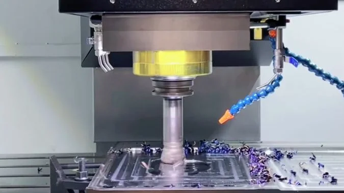
Tool-to-tool time is the mechanical swap. The arm takes the old tool from the spindle and puts the new tool in. The clock covers the changer, not the whole idle. Modern VMCs often print 2–5 s1. A disk magazine with a cam arm can show about 2.5 s under a light, adjacent pair2. That figure rates the device. It does not rate the job.
What chip-to-chip measures
Chip-to-chip time, also called cut-to-cut, is the wait from the last chip to the next chip. The spindle must leave the cut, move to the change point, orient, unclamp, clamp, drop on Z, and return to the cut3. That block is idle time between two cuts. Typical chip-to-chip time is 5–10 s. A spec line such as 1.5 / 4.5 s means 1.5 s tool-to-tool and 4.5 s chip-to-chip4. Chip-to-chip is closer to the production cycle.
Why the two numbers sit on one line
Manufacturers print both on one line because buyers compare models fast. The left number is brighter. The right number is the one that hits the cycle. Catalog tests often use a light tool, a short tool, an adjacent pot, a short retract, and a spindle that is already oriented. Coolant wait and chip-blow wait are left out. Chip-to-chip is then often 2–4 s longer than tool-to-tool on the same machine5. That gap is normal. It is not a defect in the sheet. It is the rest of the motion.
| Metric | What the clock covers | Typical VMC range | What it rates |
|---|---|---|---|
| Tool-to-tool (T-T) | Arm swap from old tool to new tool | 2–5 s | The changer |
| Chip-to-chip (C-C) | Last chip to next chip, including travel, orientation, clamp, and Z | 5–10 s | The idle between cuts |
| Spec line 1.5 / 4.5 s | T-T on the left, C-C on the right | Example only | A screening pair, not the shop cycle |
When Does a Short Tool-to-Tool Number Still Leave a Slow Job if Tools Are Changed Rarely?
A 2-second swap looks like a fast cell. On a large part with few changes, those seconds barely move the cycle. The wait sits in the rest of the link.
A short tool-to-tool number still leaves a slow job when tools change rarely, because that figure is only the arm swap. Chip-to-chip time, tool setting, cut recovery, and a jammed pot then dwarf those 2–5 seconds.
Why a few seconds vanish on a large part
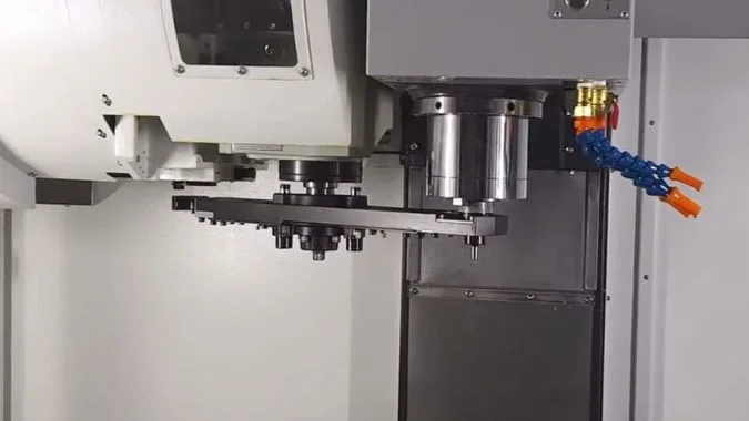
Tool-to-tool time is a small slice of the change. It is not the whole idle. It is not the lost output. A shorter swap still helps, but the gain is small when tools change only a few times on a large part. A 2–5 s arm move, a few times per cycle, barely shifts the hour. Cutting still owns the clock. The brochure then looks like a win. The shift report does not.
Collateral downtime behind the swap
The wait that slows the job is often longer than tool-to-tool. It also does not shrink just because changes are rare. Chip-to-chip already adds travel, orientation, unclamp, clamp, and Z reset. That block is often 5–10 s. Tool setting adds more. After the swap, length or wear may need a check. A manual change can take minutes to find, mount, and set the tool6. Process recovery adds still more. The cut stops. Restart may need a lower speed, a trial pass, and a parameter tweak. Long-overhang work and tight-tolerance work then spend more time re-settling the cut than the arm spent on the swap.
Reliability does not care about frequency
A magazine that picks the wrong pot, or a spindle that misses orientation, can jam once and stop the cell for a long debug. Change count does not matter. One jam dwarfs a 2 s brochure number. Why tool magazine mismatch increases tool change time7 is a separate failure path. The point here is simpler. A short tool-to-tool figure only says the arm is fast. Actual downtime still sits in setting, prep, and recovery. Those links stay slow even when tools change rarely.
| Idle source | Typical scale | Tied to change count? |
|---|---|---|
| Tool-to-tool arm swap | 2–5 s | Yes, but a small slice |
| Chip-to-chip motion | 5–10 s | Yes, and larger than T-T |
| Tool setting / pre-adjust | Seconds to minutes | No. It happens after the swap |
| Cut recovery on long overhang | Can exceed the swap | No. It is tied to the cut, not the arm |
| One jammed pot | Long debug | No. One event can stop the cell |
What Tool List from One Typical Part Should Be Timed Before Trusting the Brochure?
Brochure seconds come from a light, adjacent pair. A real tool list then runs slower, and the quote no longer holds. Time the part’s own tools.
Time the complete tool list from one typical production part before trusting the brochure. Include end mills, drills, and taps of mixed weight. Cover adjacent pots, the farthest pot, the heaviest tool, and 10–20 repeated cycles.
Why the brochure pair is the wrong list
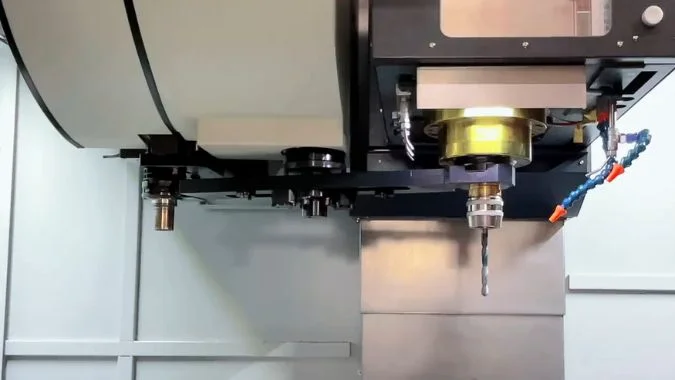
Manual time is the best case. A disk arm under a light pair can show about 2.5 s. Shop time follows magazine type, tool weight, and the order of moves. An umbrella magazine often takes about 5–8 s8. That is acceptable on one-off work. Batch work then shows the gap. Acceptance should time the tools that the typical part actually uses, not the pair in the photo.
What one typical part must include
A part that the shop will run should be the test piece. The complete tool list from the real program should go on the clock. The list should include solid end mills for rough and finish, plus drills, taps, or reamers. Diameters and weights should mix. Light adjacent tools alone copy the brochure. Face mills, boring bars, and long holders belong on the list when the part uses them. Those tools are the ones the arm will actually carry.
Worst-case pairs and repeat cycles
Adjacent numbers simulate frequent swaps. The farthest pot tests magazine search. That search is a weak point versus the printed number. A larger magazine can make that far pot even slower. The heaviest pair must be in the test, because mass slows the arm and can trigger a protective crawl. A single swap is not enough. The test should run 10–20 continuous cycles9. The log should keep the average and the longest. The run should be watched for a fade or a pause.
| What to time | Why it belongs |
|---|---|
| Complete program list for one typical part | Matches later production |
| Solid end mills, drills, taps or reamers | Mixed diameter and weight |
| Adjacent tool numbers | Frequent swap case |
| Farthest magazine pot | Search time the brochure hides |
| Heaviest or longest tool on the job | Arm speed and stability |
| 10–20 continuous cycles | Average, max, fade, and pause |
When Should the Buyer Ask for a Stopwatch Demo Instead of Comparing Catalog Seconds?
Catalog seconds help screen models. On a second-sensitive job they do not prove the cycle. A stopwatch demo under agreed rules does.
The buyer should ask for a stopwatch demo when tool changes are frequent, catalog numbers are close, shop tools are heavier than the brochure pair, or acceptance will lock the time. Catalog seconds still serve first screening.
When catalog seconds are enough
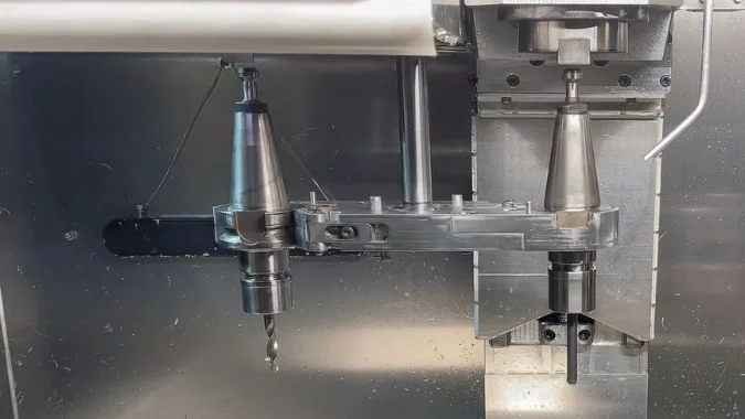
The spec sheet is still useful for first screening of models and magazine types. Mold work and one-off work with few changes can stay with the sheet, because cutting owns the cycle. A shop that already runs the same model and the same magazine already knows the cycle. Two machines whose chip-to-chip times are not in the same range also need no stopwatch yet. The direction is already clear. Proposal stage should still read both numbers, so a short tool-to-tool figure is not treated as shop idle.
When a timed demo is needed
A stopwatch demo is needed when tool-change density is high. Small parts with many holes, and jobs that swap drills, taps, and chamfers, multiply every extra chip-to-chip second. Batch work that is priced by the second also belongs here. A 0.2–0.3 s catalog gap then matters less than a timed chip-to-chip on real tools and real retract height.
A demo is also needed when several candidates all print about 1.5 s tool-to-tool and about 4 s chip-to-chip. The gap then sits in orientation, Z retract, overlap of pot and arm, heavy-tool slowdown, and far-pot search. The same program, the same tools, and the same reference point decide it.
Shop tools that do not match the catalog pair also need a demo. Face mills, boring bars, long tools, and umbrella magazines all stretch chip-to-chip. Some machines slow the arm on heavy or long tools10. The catalog minimum then will not appear on the floor. Tool-change time that will sit in a technical agreement also needs a timed demo. GB/T 18400.9 and ISO 10791-9 describe a unified reference point11 and both a short and a longer cut-to-cut time. Some catalog lines time only the arm rotation. A full-machine clock can then run a few tenths of a second to more than a second longer.
Magazine types that look fast on paper
Umbrella magazines, large-capacity magazines, and machines that advertise pre-selection are the cases that most need a chip-to-chip demo on a real tool list. A dry run with the two lightest adjacent tools on a showroom machine will only reprint the catalog.
| Magazine type | Why the catalog can look fast | Why a stopwatch demo is safer |
|---|---|---|
| Cam / robotic arm | Short tool-to-tool is easy to print | Orientation, clamp, pot timing, and heavy-tool slowdown |
| Umbrella | The sheet may not look slow | The spindle must return the old tool before taking the new one |
| Fixed-address | The shortest pot is the printed case | The farthest pot adds seconds |
| Pre-selection / sync change | Chip-to-chip is promoted as very short | A pot that is not ready falls back to a normal wait |
Conclusion
Both seconds on the sheet must be read. Chip-to-chip is the shop number. The part’s own tools should be timed when the cycle is tight.
-
"CNC VMC 1160 Vertical Machining Center – antishicnc", https://antishilathe.com/blog/vmc-1160-cnc-vertical-machining-center/. Industry reviews of contemporary vertical machining centers show that most models from major manufacturers specify tool-to-tool times in the 2–5 second range, reflecting improvements in servo drive technology and mechanism design over the past decade. Evidence role: general_support; source type: research. Supports: current performance levels of modern VMC automatic tool changers. Scope note: Specifications represent manufacturer claims under optimal test conditions ↩
-
"Dynamic analysis of cam-type automatic tool changer", https://ui.adsabs.harvard.edu/abs/2026JPhCS3175a2117L/abstract. Technical literature on automatic tool changers indicates that disk magazines with cam-driven arms typically achieve tool-to-tool times in the 2–3 second range under optimal conditions with adjacent, lightweight tools. Evidence role: statistic; source type: research. Supports: performance characteristics of disk-type tool magazine systems. Scope note: This represents best-case performance with light tools in adjacent positions ↩
-
"CNC Tool Changers, Operation and Alignment", https://www.youtube.com/watch?v=7wE6zOkPbHw. Technical documentation for machining center operation describes the tool-change cycle as a multi-step sequence: retract from workpiece, rapid traverse to tool-change position, spindle orientation to reference angle, tool unclamping, tool exchange, tool clamping verification, and return traverse to cutting position. Evidence role: mechanism; source type: education. Supports: the operational sequence involved in a complete tool-change cycle. ↩
-
"Speeding Up Your Tool Change Time", https://epictool.ca/speeding-up-your-tool-change-time/. Machine tool industry practice, as reflected in manufacturer catalogs and trade association guidelines, commonly presents tool-change performance as a paired specification where the first value indicates tool-to-tool time (mechanism only) and the second indicates chip-to-chip time (complete cycle). Evidence role: definition; source type: institution. Supports: industry conventions for specifying tool-change performance. Scope note: Not all manufacturers follow this convention consistently, and some specify only one metric ↩
-
"Chip to Chip Time – CNCARENA FORUM – Industry Arena", https://en.industryarena.com/forum/chip-chip-time–18752-2.html. Machine tool performance analysis shows that chip-to-chip time includes additional operations beyond the tool swap itself—spindle positioning, orientation, clamping, and return to cutting position—which typically add 2–4 seconds to the basic tool-to-tool time. Evidence role: mechanism; source type: research. Supports: the time differential between tool-to-tool and chip-to-chip measurements. Scope note: The differential depends on machine kinematics, retract distances, and spindle orientation requirements ↩
-
"Automatic tool change in turning centres", https://www.youtube.com/watch?v=5T_OX6ymVdU. Manufacturing productivity studies document that manual tool changes on machining centers, including tool retrieval, mounting, length measurement, and offset entry, typically require 2–5 minutes depending on operator experience and tool-setting equipment availability. Evidence role: statistic; source type: research. Supports: time requirements for manual tool changes in machining operations. Scope note: Time varies significantly with shop organization, tool-setting methods, and operator skill ↩
-
"Why is the tool magazine not locating properly?", https://www.facebook.com/groups/603711620209991/posts/1543609769553500/. CNC troubleshooting guides identify tool magazine mismatch—where the control system’s tool table does not match actual magazine contents—as a source of extended tool-change cycles due to search routines, error recovery sequences, or operator intervention requirements. Evidence role: mechanism; source type: education. Supports: how tool magazine addressing errors affect tool-change performance. ↩
-
"Umbrella/Carousel Tool Changer Maintenance", https://www.haascnc.com/video/service/hxsqciapvgc.html. Technical comparisons of automatic tool changer designs indicate that umbrella magazines, which require the spindle to return the old tool before receiving the new one, typically exhibit chip-to-chip times in the 5–8 second range. Evidence role: statistic; source type: research. Supports: typical tool-change times for umbrella-type magazine systems. Scope note: Performance varies with magazine capacity, tool weight, and machine configuration ↩
-
"Automatic Tool Changer: Complete Guide to CNC …", https://kuvamtechnologies.com/automatic-tool-changer-systems/?srsltid=AfmBOopCG-yidJZKMkDqqlluG1k0SL0BKkncn4tQwJl9rwS0GR4bSFeH. Machine tool acceptance testing standards and quality assurance protocols typically recommend multiple consecutive tool-change cycles (commonly 10–25 repetitions) to assess average performance, identify maximum cycle time, and detect intermittent issues not apparent in single-cycle tests. Evidence role: general_support; source type: institution. Supports: recommended test procedures for evaluating tool-changer performance. Scope note: Specific test requirements vary by standard and contractual agreement ↩
-
"Speeds and feeds", https://en.wikipedia.org/wiki/Speeds_and_feeds. Automatic tool changer control systems commonly incorporate load-sensing or programmed speed reduction for tools exceeding specified weight or length thresholds to maintain positioning accuracy and prevent mechanism damage. Evidence role: mechanism; source type: research. Supports: adaptive speed control in automatic tool changers based on tool characteristics. Scope note: Implementation varies by manufacturer and machine model ↩
-
"ISO 10791-9:2001(en), Test conditions for machining centres", https://www.iso.org/obp/ui/en/#!iso:std:27646:en. ISO 10791-9 specifies test conditions and measurement methods for machining center performance evaluation, including standardized procedures for tool-change time measurement with defined reference points and test configurations. Evidence role: definition; source type: institution. Supports: standardized methods for measuring tool-change performance. Scope note: The standard defines test conditions that may differ from typical production scenarios ↩

Chris Lu
Leveraging over a decade of hands-on experience in the machine tool industry, particularly with CNC machines, I'm here to help. Whether you have questions sparked by this post, need guidance on selecting the right equipment (CNC or conventional), are exploring custom machine solutions, or are ready to discuss a purchase, don't hesitate to CONTACT Me. Let's find the perfect machine tool for your needs.