

What Are the Causes of High Spindle Runout on HMC Bare Machine?
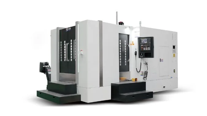
Commissioning a bare Horizontal Machining Center (HMC) requires rigorous geometric verification. If excessive spindle runout is detected during initial test cuts, it indicates underlying mechanical or structural issues that must be systematically diagnosed and resolved before moving to full-scale production.
High spindle runout on an HMC bare machine comes from worn spindle bearings, a damaged taper hole, loose drive couplings, and an unstable machine foundation. You must fix these mechanical and structural flaws to achieve perfect spindle rotation.
Isolating the root cause of spindle runout requires a systematic diagnostic approach, moving from external structural foundations up to the internal spindle components. The following technical breakdown outlines the critical inspection points and mechanical adjustments needed to eliminate runout and restore rotational precision.
What Bearing Clearances and Flaws Drive Up Spindle Runout?
When dial indicator readings show inconsistent or excessive radial deflection at the spindle nose, internal bearing degradation is a primary suspect. Maintaining strict spindle precision requires a thorough inspection of the internal bearing system to identify wear, cage damage, or improper preload settings.
Worn balls, damaged cages, and incorrect bearing preload drive up spindle runout. A radial clearance above 0.005mm causes extreme wobble. You must apply the correct axial preload and use high-precision bearings to keep the spindle perfectly centered.
Inspection Steps
Spindle bearings take heavy loads during high-speed operation. The metal balls wear down over time. The cages break. This damage ruins rotational precision. You must perform a static inspection. You turn off the power. You rotate the spindle by hand. You feel for sticking or uneven resistance. You use a dial indicator to measure the radial clearance. High-precision spindles need a clearance of 0.005mm or less.
Preload Calibration
You must calibrate the bearing preload next. Preload stops the bearings from moving around. You adjust the axial preload to two or five percent of the rated dynamic load1. You add or remove metal shims to change this pressure. I once saw a machine with terrible runout. We reapplied an axial preload of 180N. The runout dropped from 0.03mm to 0.008mm immediately.
Bearing Replacement
You must replace severely worn bearings. You buy high-precision P4 or P2 grade bearings2. You always replace them in pairs. You clean the assembly area completely. You fill the new bearing with high-temperature grease. You point the large opening of the angular contact bearing toward the heavy load direction.
| Bearing Problem | Inspection Method | Solution |
|---|---|---|
| Worn balls | Rotate spindle by hand | Replace bearings in pairs |
| Loose clearance | Use dial indicator | Add shims for preload |
| Dry bearings | Check internal grease | Add high-temperature grease |
| Wrong direction | Visual check | Point large opening to load |
Why Does a Poor Taper Fit Increase HMC Runout?
Tool eccentricity during operation often stems from a compromised taper fit rather than the tool itself. If the tool holder does not seat perfectly along the true centerline due to wear or contamination, the resulting runout will ruin the surface finish, making it essential to evaluate and correct the clamping system.
A poor taper fit increases runout because wear, dirt, or big gaps push the tool eccentric. The tool does not spin on the true centerline. You must repair taper wear and clean all surfaces to stop the tool from shaking.
Taper Hole Wear
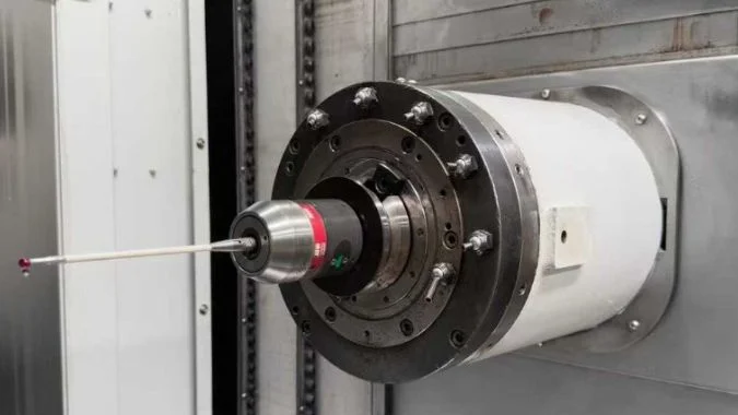
Poor tool clamping is a common issue often misattributed to general machine failure, when the root cause frequently lies within the spindle taper hole. Wear and accumulated metal chips compromise the precision fit; even a minute piece of debris can push the tool shank off-center, leading to severe runout. To resolve this, a careful inspection of the taper hole is essential. By inserting a standard test bar into the spindle and using a dial indicator to check the near end, you can ensure the radial runout stays within the critical limit of 0.005mm3.
Grinding and Repair
You must repair a worn taper hole immediately. You can grind the hole in your shop. You attach sandpaper strips to an old tool shank. You grind the inside of the spindle until the runout drops. You must use professional laser cladding for deep scratches.
Better Tool Holders
You should change your tool holder type. Spring collets cause problems. You should buy hydraulic tool holders or shrink-fit holders. These advanced holders grab the tool perfectly. They reduce runout by up to fifty percent4. You must clean the taper hole before every tool change. You must use thick tool shanks. You must keep the tool short. A short tool stops bad vibrations completely.
| Clamping Defect | Negative Result | Corrective Action |
|---|---|---|
| Metal chips in hole | Pushes tool sideways | Clean taper before clamping |
| Worn spindle taper | Tool wobbles | Grind the taper hole |
| Spring collet gap | Tool slips | Use hydraulic holders |
| Long tool stick-out | Tool vibrates heavily | Use short thick tools |
How Do Coupling Vibrations Cause Severe Spindle Runout?
Abnormal harmonics or vibrations originating from the motor housing frequently indicate power transmission irregularities. Loose drive connections or misaligned couplings transmit disruptive frequencies directly into the spindle shaft5, requiring a strict coaxiality alignment check of the entire drive train.
Coupling vibrations cause runout when loose bolts or a bad coaxiality alignment shake the power transmission system. The motor pushes vibration directly into the spindle shaft. You must tighten the coupling and align the motor precisely.
Loose Drive Couplings
The motor connects to the spindle with a coupling. This coupling must transfer power smoothly. A loose coupling generates massive vibration. This vibration travels straight into the spindle. It causes severe runout. You must check the physical coupling first. You look at the coupling bolts. You tighten them to the correct torque. The manual usually asks for forty to sixty Newton-meters.
Buffer Pad Aging
You inspect the rubber buffer pad inside the coupling. An old hard pad cannot absorb shocks. You replace the pad. You rotate the motor end by hand. You feel for a gap before the spindle moves. You must eliminate all play in this connection.
Coaxiality Calibration
You must calibrate the motor coaxiality. The motor center and the spindle center must form a perfectly straight line. You use a laser alignment tool to check this line. You adjust the motor position. You must bring the deviation under 0.005mm6. A tight transmission chain stops vibration completely. Perfect alignment guarantees a smooth spinning spindle.
| Transmission Issue | Testing Tool | Repair Step |
|---|---|---|
| Loose bolts | Torque wrench | Tighten to 50 N-m |
| Hard buffer pad | Visual inspection | Install new rubber pad |
| Motor gap | Hand rotation test | Fix coupling play |
| Bad motor alignment | Laser alignment tool | Adjust motor position |
What Structural Instabilities Lead to High Machine Runout?
An inadequate installation environment severely compromises overall machine rigidity. Without a perfectly level and securely anchored foundation, the heavy cast-iron frame can experience micro-twisting, which directly throws the spindle off its true rotational axis and degrades geometric accuracy.
Structural instabilities lead to high runout through loose anchor bolts, an unlevel foundation, and thermal deformation of the housing. These issues bend the spindle out of its true path. You must bolt the machine down tightly and manage heat.
Loose Machine Foundation
Check the ground before check the machine. The basic machine structure holds everything together. A weak foundation destroys the original rotational trajectory of the spindle. The heavy casting bends. The spindle deviates from the center. You get massive runout. You must secure the installation foundation. You check the large anchor bolts on the floor. You tighten every bolt firmly. You use a precision level to check the machine bed. An unlevel machine twists the heavy metal frame7. You must fix the whole-machine deformation first.
Thermal Deformation Control
You must control the thermal deformation. The spindle housing gets hot during operation. Uneven heat bends the metal. This thermal bending creates huge problems for precision machines. You can control this heat easily. You run the spindle with no tool for thirty minutes8. This warm-up period brings the metal to a stable temperature.
Final Runout Inspection
You must perform a final system inspection. You put a dial indicator on the spindle. The runout must measure under 0.003mm. You run the machine at different speeds. You listen for bad noises. You use a vibration meter. You must keep the radial vibration velocity under 1.0 mm/s.
| Structural Problem | Symptom on Machine | Fix Method |
|---|---|---|
| Loose anchor bolts | Whole machine shakes | Tighten floor bolts |
| Unlevel bed | Casting twists | Use precision level |
| Cold spindle start | Metal bends unevenly | Run 30-minute warm-up |
| High vibration | Runout > 0.003mm | Check with vibration meter |
Conclusion
You must fix bearings, tapers, couplings, and foundations to eliminate HMC spindle runout. Regular maintenance and careful alignment guarantee a perfectly centered spindle and high-quality parts.
-
"[PDF] Life and Load Ratings – Angular Contact Ball Bearings", https://dpk3n3gg92jwt.cloudfront.net/domains/ast_units/pdf/ENB-04-0723.pdf. A bearing design reference should describe preload selection for angular-contact spindle bearings and relate preload magnitude to a percentage or fraction of bearing load rating; this supports the preload-sizing concept but may not validate the exact 2–5% value for all spindle assemblies. Evidence role: mechanism; source type: research. Supports: You adjust the axial preload to two or five percent of the rated dynamic load.. Scope note: Preload recommendations vary with bearing arrangement, speed, lubrication, and thermal conditions. ↩
-
"Tolerances | SKF", https://www.skf.com/us/products/rolling-bearings/principles-of-rolling-bearing-selection/general-bearing-knowledge/tolerances. An ISO or bearing-class reference should define P4 and P2 precision classes for rolling bearings and show that these classes specify tighter dimensional and running tolerances than ordinary grades; this supports the meaning of the precision designation, not the necessity of replacement in every case. Evidence role: definition; source type: institution. Supports: You buy high-precision P4 or P2 grade bearings.. Scope note: The source establishes bearing precision grades but does not prove that P4 or P2 is required for every HMC spindle. ↩
-
"Using a Test Bar to Check Spindle Run out – YouTube", https://www.youtube.com/watch?v=Pepl4kIbyjM. A machine-tool test standard or spindle inspection guide should specify allowable radial runout limits when measuring a spindle with a test bar; this supports the cited 0.005 mm criterion only if the measurement setup and machine accuracy class match the article’s context. Evidence role: statistic; source type: institution. Supports: By inserting a standard test bar into the spindle and using a dial indicator to check the near end, you can ensure the radial runout stays within the critical limit of 0.005mm.. Scope note: Runout limits depend on test-bar length, indicator position, spindle taper, and acceptance standard. ↩
-
"Comparing Tool Holders: Nut and Collet, Hydraulic … – YouTube", https://www.youtube.com/watch?v=pNIL2D3W3TY. An independent tooling study should compare runout values for collet, hydraulic, and shrink-fit holders and report whether hydraulic or shrink-fit systems can materially reduce runout; this supports the comparative claim only if the tested holders and cutting conditions are similar. Evidence role: statistic; source type: paper. Supports: Hydraulic tool holders or shrink-fit holders reduce runout by up to fifty percent.. Scope note: The exact percentage reduction is application-dependent and may not generalize across all holder types or tool diameters. ↩
-
"[PDF] an analysis of the impact of flexible coupling misalignment – OAKTrust", https://oaktrust.library.tamu.edu/bitstream/handle/1969.1/ETD-TAMU-2010-08-8315/AVENDANO-OVALLE-THESIS.pdf?sequence=2&isAllowed=y. A rotating-machinery or machine-tool dynamics source should explain that coupling looseness and shaft misalignment introduce vibration components that can be transmitted through the drive train; this supports the vibration-transmission mechanism but may not show direct spindle runout measurements. Evidence role: mechanism; source type: paper. Supports: Loose drive connections or misaligned couplings transmit disruptive frequencies directly into the spindle shaft.. Scope note: The evidence may address rotating machinery generally rather than HMC spindles specifically. ↩
-
"[PDF] CALCULATING SHAFT COUPLING MISALIGNMENT FORCES IN …", https://oaktrust.library.tamu.edu/server/api/core/bitstreams/9f405a46-15e5-4350-ae10-026ff328cc5c/content. A precision alignment or machine-tool assembly reference should state typical coaxiality tolerances for motor-spindle alignment or comparable high-speed shaft alignment; this supports the need for tight alignment but may not validate 0.005 mm as universal. Evidence role: statistic; source type: research. Supports: You must bring the motor-to-spindle coaxiality deviation under 0.005mm.. Scope note: Acceptable coaxiality depends on coupling type, spindle speed, bearing arrangement, and machine design. ↩
-
"[PDF] Prediction of geometric-thermal machine tool errors by artificial …", https://nvlpubs.nist.gov/nistpubs/Legacy/IR/nistir5367.pdf. A machine-tool installation or geometric accuracy source should explain that improper leveling and foundation support can deform the machine structure and alter geometric accuracy; this supports the structural-deformation claim but may not isolate spindle runout as the only outcome. Evidence role: mechanism; source type: government. Supports: An unlevel machine twists the heavy metal frame.. Scope note: The source may discuss overall geometric error rather than spindle runout alone. ↩
-
"[PDF] THERMAL MODELLING OF HIGH SPEED MACHINE TOOL …", https://research.sabanciuniv.edu/32397/1/TurgutKoksalYalcin_10099905.pdf. A machine-tool thermal-error study or spindle warm-up procedure should show that spindle warm-up reduces transient thermal deformation by moving the machine toward thermal equilibrium; this supports the rationale for warm-up, while the exact 30-minute duration remains machine-specific unless directly stated. Evidence role: mechanism; source type: paper. Supports: You run the spindle with no tool for thirty minutes to bring the metal to a stable temperature.. Scope note: Warm-up time varies with spindle speed, bearing design, coolant, and ambient conditions. ↩

Chris Lu
Leveraging over a decade of hands-on experience in the machine tool industry, particularly with CNC machines, I'm here to help. Whether you have questions sparked by this post, need guidance on selecting the right equipment (CNC or conventional), are exploring custom machine solutions, or are ready to discuss a purchase, don't hesitate to CONTACT Me. Let's find the perfect machine tool for your needs.