

What Is the Function of the Guide Bushing in a CNC Swiss-Type Lathe?
Long bar stock can bend under cutting force1. That movement causes vibration, taper, poor finishes, and rejected precision parts.
A guide bushing supports bar stock close to the cutting tool in a CNC Swiss-type lathe. It shortens the unsupported length, limits bending and vibration, guides radial movement, and helps the machine produce accurate long, slender parts.
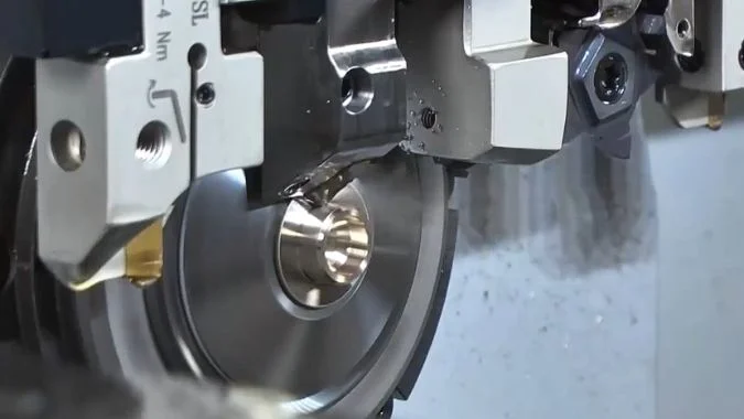
By supporting the bar stock directly next to the cutting tool, the guide bushing prevents deflection and vibration on long, slender parts.Because part geometries, finishes, and production costs vary, Swiss-type lathes offer different support options to handle distinct machining challenges.
What Are the Different Types of Guide Bushings for CNC Swiss-Type Lathes?
Using one setup for every part can raise material costs or lower accuracy. An unsuitable support mode can also cause scratches, vibration, and bushing failure.
CNC Swiss-type lathes use three main operating modes: rotating guide bushing, fixed guide bushing, and non-guide-bushing mode. Rotating and fixed bushings support slender parts near the tool. Non-guide-bushing mode removes this support and is mainly used for short parts.
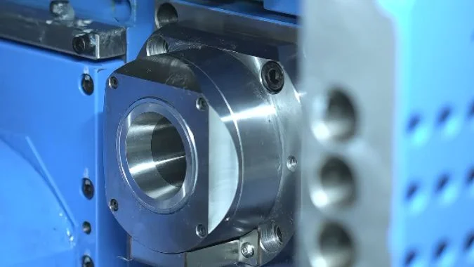
How Does Each Mode Support the Bar?
A rotating guide bushing connects to the main spindle through a drive system2. The system may include shafts, gears, or timing belts. The bushing rotates at nearly the same speed as the spindle and bar. This synchronized movement limits sliding friction between the bar surface and the bushing bore3. It works well for long parts, higher spindle speeds, and surfaces that must remain free from guide marks.
A fixed guide bushing remains stationary while the spindle and bar rotate. Its bore gives firm radial support close to the tool. The simple support structure can provide very stable positioning. However, the rotating bar slides against the stationary bore. The contact area needs a steady oil film4. Bar straightness, roundness, and diameter control are also important.
Non-guide-bushing mode removes the front support. The main spindle collet holds the material, and the cutting point stays close to the collet. This arrangement reduces remnant length and simplifies the bar path. It is suitable for short parts that have enough natural rigidity.
| Mode | Bushing movement | Main support method | Typical L/D range |
|---|---|---|---|
| Rotating guide bushing | Rotates with the spindle | Near-point support with low relative rotational friction | Usually above 35 |
| Fixed guide bushing | Remains stationary | Near-point support through a fixed precision bore | Usually above 3 |
| Non-guide-bushing mode | No guide bushing is used | Spindle collet supports the workpiece | Usually below 3–3.5 |
The length-to-diameter ratio is a starting point rather than an absolute rule. Material hardness, cutting depth, tool position, spindle speed, and required tolerance can change the final choice.
What Are the Advantages and Disadvantages of the Three Types of Guide Bushings for CNC Swiss-Type Lathes?
The wrong bushing mode can hide costs inside scrap, downtime, and wasted bar ends. A clear comparison prevents these losses before production begins.
Rotating bushings support high-speed cutting with less surface friction but cost more. Fixed bushings can provide strong precision but need good bar quality and lubrication. Non-guide-bushing mode saves material but offers less support for slender workpieces.
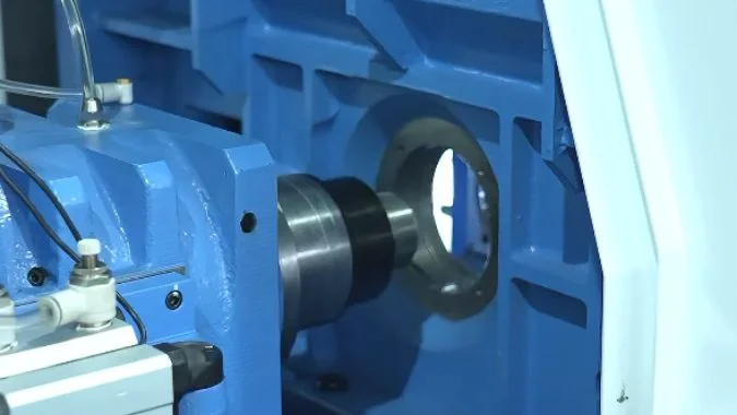
Rotating Guide Bushing
The main benefit of a rotating bushing is synchronized motion. The bushing and bar turn together, so the bar does not rub heavily around the inner bore during rotation. This lowers the risk of scratches, heat, and seizure. It also allows relatively high spindle speeds. Slight bar straightness errors are often easier to manage than with a fixed bushing.
The mechanism has more parts. Bearings, belts, shafts, seals, and coupling parts increase the purchase and maintenance cost. Transmission wear or belt slip can create a speed difference between the bushing and spindle. That difference can mark the surface or reduce dimensional stability. The guide bushing assembly also creates a longer distance between the collet and cutting area. More bar must remain at the end of a production run, so material use is lower. A rotating system may also provide slightly lower positioning stability than a properly adjusted fixed bushing in some precision applications.
Fixed Guide Bushing
A fixed bushing has a simpler structure and can offer firm radial control. It is often selected for medium or lower speed machining where very stable support is required. Maintenance costs for the drive system are lower because no synchronized bushing drive is needed.
Relative friction is its main limit. The bar rotates inside a stationary hole. A continuous oil film must separate both surfaces. Poor lubrication can cause heat, scratches, jamming, or a burned bushing6. High spindle speed increases this risk. The raw bar also needs good straightness, roundness, and diameter consistency. Like the rotating type, it leaves a longer remnant.
Non-Guide-Bushing Mode
This mode provides the shortest remnant, sometimes close to 30 mm on a suitable machine7. It offers high material use and fast response for short parts. However, it gives no support beside the cutting point. Excessive overhang can cause deflection, chatter, taper, tool damage, and higher spindle-bearing loads8.
| Mode | Main advantages | Main disadvantages |
|---|---|---|
| Rotating | High-speed capability, low rotational friction, fewer surface scratches, lower bar-straightness demand | Higher cost, complex drive, long remnant, transmission maintenance |
| Fixed | Stable radial support, high precision potential, simpler mechanism | Needs good bar quality, constant lubrication, speed limits, long remnant |
| Non-guide | Short remnant, high material use, simple bar path | Weak support, limited part length, higher spindle load, greater vibration risk |
What Kind of Workpieces Are Each of the Three Types of Guide Bushings Suitable For?
A part may look simple in a drawing but behave differently during cutting. Length, diameter, hardness, speed, and surface requirements all affect rigidity.
Rotating guide bushings suit long parts cut at high speed. Fixed guide bushings suit long, accurate parts produced at controlled speeds. Non-guide-bushing mode suits short, rigid parts where material savings and fast production are important.
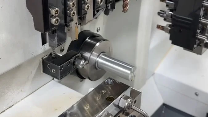
Selection by Length, Speed, and Surface Requirements
A rotating guide bushing is normally suitable for slender shafts with a length-to-diameter ratio above 3. Common examples include medical pins, connector pins, small motor shafts, valve stems, long screws, and precision instrument parts9. It is also useful when high spindle speed is needed. Synchronous rotation helps protect polished or coated bar surfaces from rotational scratches. Bars with moderate straightness variation may run more reliably in this mode, although badly bent material remains unsuitable.
A fixed guide bushing also supports workpieces with a length-to-diameter ratio above 3. It fits parts that need stable radial guidance and tight dimensional control at medium or lower speeds. Ground bar stock with good straightness and a consistent diameter gives the best result. Hard materials can be machined in this mode when lubrication, clearance, and cutting parameters are controlled. A fixed bushing is less suitable when the bar surface is highly sensitive to rubbing marks.
Non-guide-bushing mode suits short pins, nuts, spacers, washers, short connectors, and flat or compact components. The common range is below an L/D ratio of 3, although some stable processes may reach about 3.5. The actual limit depends on material stiffness and cutting force.
| Production condition | Preferred mode | Main reason |
|---|---|---|
| L/D above 3 with high spindle speed | Rotating guide bushing | Near-tool support with low rotational friction |
| L/D above 3 with very tight size control | Fixed guide bushing | Stable radial guidance |
| Scratch-sensitive bar surface | Rotating guide bushing | Bushing and bar rotate together |
| Short parts with high material cost | Non-guide-bushing mode | Short bar remnant |
| Poor bar straightness | Rotating guide bushing | Better tolerance of moderate variation |
| Ground, straight, round bar | Fixed guide bushing | Good fit inside the precision bore |
| Short, rigid mass-production parts | Non-guide-bushing mode | Simple setup and high material use |
Part length alone should not control the decision. A short part made from a difficult material may still create high cutting force. A long part with a small cutting depth may remain stable under controlled conditions. A trial cut should check diameter change, taper, roundness, finish, tool load, and spindle temperature. Machines that allow conversion between guide-bushing and non-guide-bushing modes provide more flexibility for mixed orders.
How Should the Daily Maintenance for Each of the Three Guide Bushings Be Performed?
Small chips, low oil flow, or a loose belt can quickly damage a precision setup. Missed daily checks can lead to burns, scratches, and unplanned downtime.
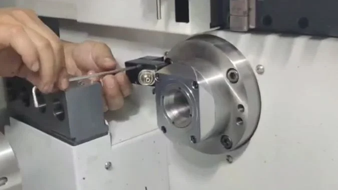
Rotating bushings need drive and bearing checks. Fixed bushings need bore cleaning and continuous lubrication. Non-guide-bushing setups need collet and spindle-front checks. Every mode also needs chip removal, coolant inspection, and regular fastening checks.
Rotating Guide Bushing Maintenance
The operator should inspect timing belts, drive shafts, and coupling parts before production. Belt tension should meet the machine maker’s specification. Cracks, polished belt teeth, loose pulleys, or abnormal vibration can show drive wear. The guide bushing speed must remain synchronized with the spindle speed. Slip creates relative movement and may scratch the workpiece.
Guide-bushing bearings need the specified grease, oil, or oil mist. The wrong lubricant can increase heat or damage seals. Abnormal noise and rising housing temperature can show early bearing failure. Labyrinth seals and nearby grooves should stay free from fine chips. The collet or bushing insert should move smoothly and should not have excessive clearance.
Fixed Guide Bushing Maintenance
The bore should be cleaned every shift with a soft, non-scratching tool. Embedded chips and dried oil can score the bar or block movement. Hard steel picks should not touch a precision bore.
The lubrication path needs daily inspection. Oil mist or drip oil must reach the contact area before the spindle starts at production speed. A weak or broken oil film can burn the bushing. The inner diameter, roundness, and clearance should be measured at planned intervals. Excessive clearance reduces support and allows taper or chatter.
Non-Guide-Bushing Mode Maintenance
The spindle collet becomes the main support point. Its clamping force, runout, wear, and opening action need frequent checks. Chips around the collet can cause poor seating or bar slippage. Spindle-front temperature and vibration should also be monitored because cutting force acts closer to the bearings without guide-bushing support.
Coolant must remove chips from the cutting and cutoff areas. Wrapped chips can scratch finished surfaces or enter the spindle-front area.
| Frequency | Maintenance task |
|---|---|
| Every shift | Remove chips, wipe coolant residue, and inspect the cutting area |
| Daily | Check oil level, lubricant flow, coolant flow, and abnormal noise |
| Daily for rotating mode | Check belt condition, synchronization, seals, and bearing temperature |
| Daily for fixed mode | Clean the bore and confirm a continuous oil film |
| Daily for non-guide mode | Check collet grip, spindle-front vibration, and chip buildup |
| Weekly | Check support frames, locking nuts, hoses, and critical fasteners |
| At planned intervals | Measure bore wear, collet runout, spindle condition, and drive wear |
Maintenance limits and lubricant grades should always follow the machine and bushing manufacturer’s instructions. A written inspection record can show gradual changes before they become production failures.
Conclusion
A guide bushing supports bar stock near the tool. The correct rotating, fixed, or non-guide mode balances precision, speed, surface quality, maintenance, and material use.
-
"Boring Bar Deflection Calculator", https://www.firgelliauto.com/blogs/engineering-calculators/boring-bar-deflection-calculator?srsltid=AfmBOoqBKtnzOPUcih1viGFmyZPyIPNTJhMpPILR8d16DZg_NAFduwEy. Research on machining dynamics confirms that cutting forces cause elastic deflection in slender workpieces, with deflection magnitude proportional to unsupported length and inversely proportional to material stiffness, resulting in dimensional errors and surface finish degradation. Evidence role: mechanism; source type: research. Supports: that unsupported bar stock experiences deflection under cutting forces, leading to dimensional inaccuracy and vibration. Scope note: The citation supports the general mechanism but does not quantify specific deflection values for Swiss-type lathe operations ↩
-
"Understanding the Main Spindle Collet, Sub Spindle Collet …", https://www.youtube.com/watch?v=ReuHjIOOTeY. Technical documentation on Swiss-type lathes describes rotating guide bushing systems that employ timing belts, gears, or shaft couplings to maintain rotational synchronization between the guide bushing and main spindle, minimizing relative motion between the workpiece and support surface. Evidence role: mechanism; source type: education. Supports: that rotating guide bushings are mechanically coupled to the spindle through transmission elements to maintain synchronization. ↩
-
"Rotational synchronization of camphor ribbons", https://pubmed.ncbi.nlm.nih.gov/30780363/. Tribological principles establish that friction and wear are functions of relative sliding velocity between contact surfaces; when rotational speeds are synchronized, relative motion approaches zero, reducing sliding friction to primarily residual effects from speed mismatch and surface roughness interactions. Evidence role: mechanism; source type: research. Supports: that synchronized rotation minimizes relative sliding velocity and thereby reduces friction and wear. ↩
-
"Synergistic Tribological Enhancement of Bushings Via …", https://ui.adsabs.harvard.edu/abs/2025JMEP..tmp.1428C/abstract. Bearing lubrication theory demonstrates that when a shaft rotates within a stationary bushing, hydrodynamic or boundary lubrication regimes must be maintained through continuous lubricant supply to separate surfaces, prevent adhesive wear, and dissipate frictional heat. Evidence role: mechanism; source type: research. Supports: that a continuous lubricant film is necessary to prevent metal-to-metal contact in configurations with relative rotational motion. ↩
-
"Long Length-to-Diameter Ratios", https://www.unitedcenterlessgrinding.net/blog/swiss-precision-machining-for-parts-with-long-length-to-diameter-ratios. Manufacturing engineering guidelines identify workpieces with length-to-diameter ratios exceeding 3:1 as slender components susceptible to significant deflection under cutting forces, typically requiring auxiliary support such as steady rests, center supports, or guide bushings to maintain dimensional accuracy. Evidence role: general_support; source type: education. Supports: that workpieces with length-to-diameter ratios above approximately 3 are considered slender and prone to deflection requiring additional support. Scope note: The exact threshold varies with material properties, cutting conditions, and tolerance requirements rather than being a fixed universal value ↩
-
"Lubricant Failure = Bearing Failure", https://www.machinerylubrication.com/Read/1863/lubricant-failure. Tribological research on bearing failures demonstrates that inadequate lubrication allows asperity contact and adhesive interactions, generating frictional heat that can exceed material tempering temperatures, cause surface scoring, promote material transfer, and in severe cases lead to thermal seizure. Evidence role: mechanism; source type: research. Supports: that insufficient lubrication leads to increased friction, heat generation, surface damage, and potential seizure in sliding bearing contacts. ↩
-
"Do machines really NEED a spindle? | Changing over to NON …", https://www.youtube.com/watch?v=A06XLn_-aSU. Swiss-type lathe specifications indicate that non-guide-bushing operation typically achieves shorter bar remnants, with values commonly ranging from 30 to 50 mm depending on machine design, compared to 80 to 150 mm typical for guide bushing configurations due to the reduced distance between collet and tool. Evidence role: statistic; source type: other. Supports: that non-guide-bushing configurations can achieve shorter bar remnants compared to guide bushing modes. Scope note: The exact minimum remnant varies significantly with machine model, spindle design, and part-off tool configuration ↩
-
"Investigation of spindle bearing preload on dynamics and …", https://mtrc.utk.edu/wp-content/uploads/sites/45/2019/09/ozturk_kumar_turner_schmitz_preload.pdf. Machine tool dynamics analysis shows that when cutting forces act on an unsupported cantilever workpiece extending from the spindle, the resulting bending moment is transmitted through the collet to the spindle bearings, with magnitude proportional to the distance from cutting point to bearing location. Evidence role: mechanism; source type: education. Supports: that removing intermediate support increases the moment arm of cutting forces, thereby increasing loads on spindle bearings. ↩
-
"Swiss-Type CNC Lathe for Medical & Automotive …", https://cncwmt.com/qa/why-swiss-type-cnc-lathe-is-the-ideal-choice-for-medical-device-and-automotive-component-manufacturing/. Manufacturing industry surveys identify Swiss-type turning as a primary production method for high-precision slender components in medical devices (surgical pins, implant components), electronics (connector contacts), automotive (fuel system components), and instrumentation sectors due to the technology’s capability for tight tolerances on small-diameter long parts. Evidence role: case_reference; source type: other. Supports: that Swiss-type turning with guide bushing support is widely applied in medical device, electronics connector, and precision mechanical component manufacturing. Scope note: The citation supports general application areas but does not specifically distinguish between rotating and fixed guide bushing modes for each component type ↩

Chris Lu
Leveraging over a decade of hands-on experience in the machine tool industry, particularly with CNC machines, I'm here to help. Whether you have questions sparked by this post, need guidance on selecting the right equipment (CNC or conventional), are exploring custom machine solutions, or are ready to discuss a purchase, don't hesitate to CONTACT Me. Let's find the perfect machine tool for your needs.