

What Should a Tapping Trial Prove Before You Buy a Tapping Center?
A demonstration can produce one acceptable thread and leave batch performance unknown. A production trial gives the buyer measured results to use in machine acceptance.
A tapping trial should prove that the tapping center can produce conforming threads on a representative production part, meet the agreed cycle time, and maintain quality across consecutive parts. The buyer and supplier should agree on the material, tooling, inspection method, run length, and pass criteria before the trial.
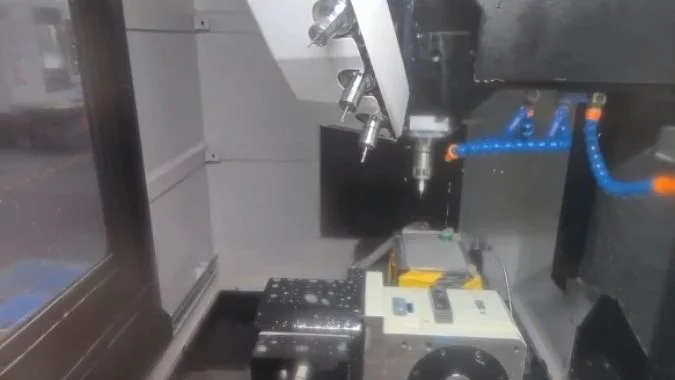
A production drawing gives the trial a starting point. It identifies the threads, their locations, and the features that must fit or assemble. The same part also brings the fixture, hole pattern, and tool sequence into the comparison. A representative trial part exposes the demands the tapping center will face on a normal production day.
Which Production Part Should You Use to Compare Two Tapping Centers?
An easy demonstration piece can hide delays and dimensional problems. A representative part gives both tapping centers the same work to complete.
The comparison should use a regular production part with a demanding mix of threaded holes, tight position tolerances, and the normal tool sequence. Both machines should use comparable material, workholding, tooling, and hole preparation. The trial should include thin walls or deep blind threads when they recur in production.
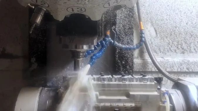
The part should contain the features that drive production
A high-volume housing or bracket with many threaded holes1 can reveal positioning time and consistency across a hole pattern. The tightest recurring position tolerance gives the inspection a specific feature to check. A thin wall can expose distortion from the fixture or machining2.
| Production feature | What it reveals in the trial |
|---|---|
| Closely spaced small threaded holes | Positioning time between holes and consistency of thread fit |
| Deep blind threads3 | Full thread depth, chip control, and reliable retract |
| Holes spread across the part | Hole position across the working area |
| Thin walls or uneven support | Deflection and distortion under the intended clamping conditions |
| Drilling, chamfering, and tapping in one setup | Tool changes and elapsed time for the planned operation sequence |
Both machines need comparable inputs
The trial sheet should identify the drawing revision, material lot, tap and holder, coolant, and fixture setup. The comparison should use tools in comparable condition and the same hole order, tapping speeds, and clearance requirements. Each control can run an equivalent program for the agreed process.
A tapping-only trial should start with equivalent pilot holes. A drill-and-tap trial should start with equivalent blanks and include hole preparation. Any later trial with machine-specific settings should record those changes so the buyer can see which process produced each result.
How Should You Time the Full Tapping Sequence from the First Hole to the Final Retract?
A cutting-time figure can understate the time spent on a hole pattern. Defined start and end events make the elapsed times comparable.
The clock starts when the first tapping cycle begins at the agreed approach position. It stops when the tap reaches the agreed return plane after the final hole. Elapsed time includes synchronized tapping and withdrawal, moves between holes, and any tool changes within that window.
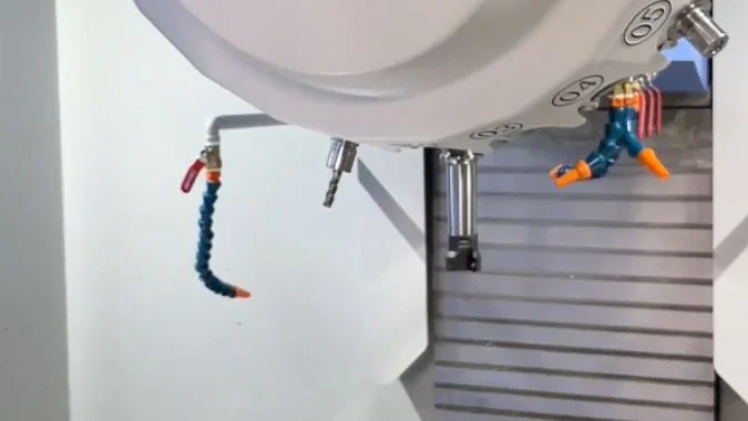
The timer follows the programmed sequence
Both tapping centers should start with the same tool readiness and spindle state. The trial plan should state the initial and final Z positions. A return to the R plane can take a different amount of time from a return to a higher initial plane.
| Timing segment | Events within the segment |
|---|---|
| First-hole start | The tap is above the first hole at the agreed approach position and the cycle begins |
| Single-hole cycle | Approach, synchronized downfeed, reversal, any programmed dwell, and return |
| Between holes | X/Y positioning and clearance moves outside the individual hole cycles |
| Tool change, if required | Each change that occurs after the first-hole start and before the final return |
| Final retract | The tap reaches the agreed return position after the last hole and the cycle reaches the defined end state |
The sequence time and part time answer different questions
The CNC event log can record the full sequence4 and show where time is spent. A stopwatch can also capture elapsed time if the operator uses the same start and finish signals on both machines. The elapsed interval counts overlapping motion once.
The trial should record several runs. The report should show the time range and the result used for acceptance, such as the slowest run. A separate production cycle can include drilling, chamfering, and routine loading or unloading. Initial tool setting and fixture preparation belong in the setup record.
How Should You Verify Thread Quality Across Consecutive Parts?
The first part can pass while later parts drift as the machine warms5 or the tap wears6. A numbered run makes those changes visible.
Thread quality should be verified on consecutive, numbered parts with calibrated GO and NO-GO thread plug gauges matched to the drawing. The inspection plan should also cover full thread depth, location, and visible damage. Measurements across the run help reveal drift and changes after a tool or offset adjustment.
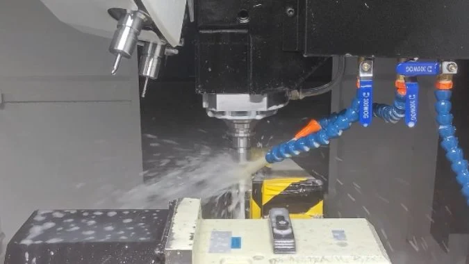
Plug gauges check the internal thread fit
The gauge size, pitch, and tolerance class should match the drawing. For a specified metric internal thread of class 6H7, the gauge should be suitable for that class. The inspector should apply the gauges by hand without forcing them. The GO gauge should engage the required threaded length. The applicable gauging standard and drawing determine the permitted NO-GO engagement.
| Check | Evidence to record |
|---|---|
| GO and NO-GO thread plug gauge | Pass or fail by part number and critical hole |
| Full thread depth | Depth measured from the specified face using the agreed method |
| Hole position and orientation | Results relative to the drawing datums using an agreed measurement method |
| Thread appearance | Torn flanks, damaged crests, burrs, or other specified defects |
| Additional thread geometry, when specified | Pitch diameter, pitch, or profile measured by a method suited to internal threads |
The run keeps each part in production order
An agreed trial might include 25 consecutive parts. The inspector should check the first piece against the full inspection plan and record gauge results for each critical thread on every part. The count and inspection frequency should be set before machining.
The record should tie measurements to part number, hole location, elapsed run time, and tool history. An offset change or tap replacement should appear at the point where it occurred. Measurements from the start, middle, and end help distinguish a gradual drift from an isolated failure.
What Tapping Trial Results Should You Include in the Machine Acceptance Criteria?
A trial report can contain good measurements and still leave acceptance open to debate. Each required result needs an agreed method and pass limit.
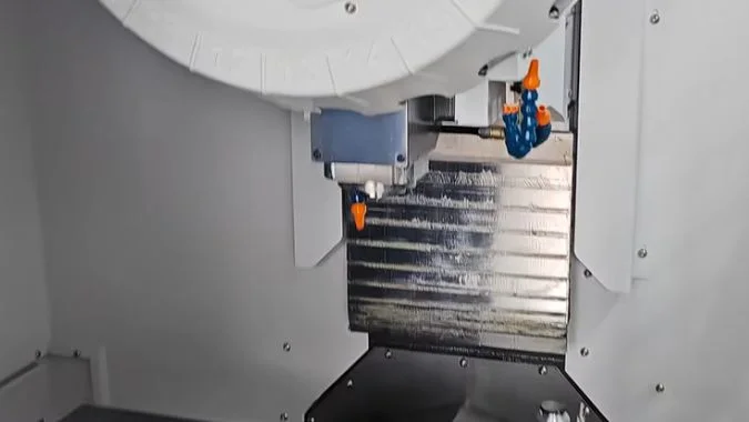
Machine acceptance criteria should include drawing conformity, thread gauge results, maximum tapping sequence time, and consistency over an agreed consecutive run. The plan should define the test setup, sample size, inspection methods, and permitted drift. Any endurance test should specify its duration, production load, and allowed interruptions.
Each acceptance item needs a measurable limit
The buyer and supplier should agree on the part, tooling, program revision, and cycle boundaries before the test. The drawing defines the part requirements. The purchase agreement defines the required output and the conditions under which the machine must deliver it.
| Acceptance item | Evidence in the report | Agreed requirement |
|---|---|---|
| Thread fit and depth | Gauge results and depth readings by hole and part | Drawing class, gauging rule, and minimum full thread depth |
| Position and profile | Datum-based measurements and defect inspection | Drawing tolerances and specified finish or defect limits |
| Tapping and part cycle time | Timed runs with defined start and end events | Agreed time limit for each required cycle |
| Consecutive part consistency | Inspection records in production order | Required sample count, pass rule, and allowed dimensional drift |
| Continuous operation | Run log, temperatures, alarms, stops, and lubrication checks | Agreed duration, duty, and permitted interruptions |
Machine measurements have their own acceptance conditions
A production trial measures the finished part under the agreed process. If axis positioning, repeatability, or spindle runout8 are purchase requirements, the agreement should state their measurement methods, test positions, and limits as separate acceptance items.
A two-shift production run is one possible endurance test9. The agreement should define the duty, warm-up condition, and when critical features will be measured again. The report should show planned tool changes, unplanned stops, and dimensional readings taken at the agreed points in the run. Any failure should stay in the record with the corrective action and the agreed retest result.
Conclusion
Acceptance should depend on conforming consecutive parts, measured cycle time, and stability under the agreed production conditions. Each pass limit belongs in the trial plan before cutting begins.
-
"Drilling and Tapping Referencing | CNC Precision Machining", https://parts-badger.com/drilling-and-tapping-referencing/. Tapping centers are commonly employed in high-volume production of components such as automotive housings, hydraulic manifolds, and structural brackets that require multiple threaded holes with precise positioning, representing a significant application segment in industries requiring efficient and accurate thread production. Evidence role: general_support; source type: other. Supports: the prevalence of multi-hole threaded parts in tapping center applications. Scope note: This characterization reflects general industry practice but does not quantify the proportion of tapping center applications devoted to multi-hole parts. ↩
-
"Correcting distortions of thin-walled machined parts by …", https://www.sciencedirect.com/science/article/pii/S1000936123003722. Thin-walled workpieces experience greater deflection under clamping and cutting forces due to reduced structural rigidity, making them prone to dimensional errors and distortion that can exceed tolerance limits if fixturing and machining parameters are not carefully controlled. Evidence role: mechanism; source type: education. Supports: the susceptibility of thin-walled parts to distortion during machining operations. Scope note: The source addresses general principles but may not quantify distortion thresholds for specific wall thickness ratios or materials. ↩
-
"Blind Hole Tapping Guide: Machine Blind Holes in Engineering", https://www.uneedpm.com/blind-hole-tapping-guide-machine-blind-holes-in-engineering/. Deep blind hole tapping requires effective chip evacuation to prevent chip packing at the bottom of the hole, which can cause tap breakage, incomplete threads, or difficulty in tool retraction, with challenges increasing as the depth-to-diameter ratio exceeds 2.5 to 3 times the hole diameter. Evidence role: general_support; source type: education. Supports: the technical challenges associated with tapping deep blind holes. Scope note: The source provides general guidance but specific depth limits vary with material, tap design, and coolant delivery method. ↩
-
"Time.gov", https://www.time.gov/. Contemporary CNC controls typically include event logging and cycle monitoring functions that record machining operations, timing data, and system events, enabling process analysis and documentation, though specific capabilities vary by control manufacturer and model. Evidence role: general_support; source type: education. Supports: the data logging capabilities of modern CNC machine controls. Scope note: The source describes general capabilities but does not address all proprietary logging formats or data accessibility methods across different control systems. ↩
-
"Machine Tool Thermal Error Measurement and Prediction …", https://www.nist.gov/publications/machine-tool-thermal-error-measurement-and-prediction-wireless-microscope. Thermal expansion of machine tool structures, spindles, and linear motion systems during operation can cause positioning errors and dimensional variations, with thermal effects accounting for a significant portion of total machining errors in precision operations, particularly during warm-up periods and under varying thermal loads. Evidence role: mechanism; source type: research. Supports: the effect of thermal expansion on machine tool accuracy. Scope note: The magnitude of thermal error depends on machine design, environmental control, and operating conditions, making quantitative predictions machine-specific. ↩
-
"Revealing the wear characteristics, mechanisms, and …", https://www.sciencedirect.com/science/article/abs/pii/S0301679X25011041. Tap wear occurs through abrasion, adhesion, and edge chipping at the cutting edges, leading to gradual changes in thread dimensions, increased cutting forces, and eventual thread quality degradation, with wear rate dependent on workpiece material, cutting speed, lubrication, and tap coating. Evidence role: mechanism; source type: education. Supports: the progression of tap wear and its effect on thread quality. Scope note: Specific tool life and wear patterns vary widely with application parameters and cannot be generalized without testing under actual production conditions. ↩
-
"ISO 965", https://en.wikipedia.org/wiki/ISO_965. ISO 965-1 defines tolerance class 6H as a medium tolerance grade for metric internal threads, where ‘6’ indicates the tolerance grade and ‘H’ indicates the fundamental deviation, representing a commonly specified fit for general-purpose threaded connections. Evidence role: definition; source type: institution. Supports: the definition and application of tolerance class 6H for metric internal threads. ↩
-
"ISO 230-1:2012 – Test code for machine tools — Part 1", https://www.iso.org/standard/46449.html. ISO 230 series standards provide internationally recognized test methods for evaluating machine tool performance, including positioning accuracy and repeatability of linear and rotary axes, while spindle runout is typically measured according to ISO 230-7 or equivalent standards using dial indicators or non-contact sensors. Evidence role: general_support; source type: institution. Supports: standardized methods for measuring machine tool positioning accuracy, repeatability, and spindle runout. ↩
-
"Qualification for AM Feedstocks, Machines and Processes", https://www.nist.gov/programs-projects/qualification-am-feedstocks-machines-and-processes. Machine tool acceptance protocols often include endurance or capability tests that run for extended periods under production conditions to verify thermal stability, sustained accuracy, and reliability, with durations ranging from several hours to multiple shifts depending on contractual requirements and industry practice. Evidence role: general_support; source type: institution. Supports: the use of extended production runs in machine tool acceptance procedures. Scope note: Specific endurance test durations are typically negotiated between buyer and supplier rather than prescribed by universal standards. ↩

Chris Lu
Leveraging over a decade of hands-on experience in the machine tool industry, particularly with CNC machines, I'm here to help. Whether you have questions sparked by this post, need guidance on selecting the right equipment (CNC or conventional), are exploring custom machine solutions, or are ready to discuss a purchase, don't hesitate to CONTACT Me. Let's find the perfect machine tool for your needs.